Makecode Tutorial
Resource Download
To help you quickly obtain related codes, libraries, and other support files for this product, please click the links below to download:
1.Getting Started with Micro:bit
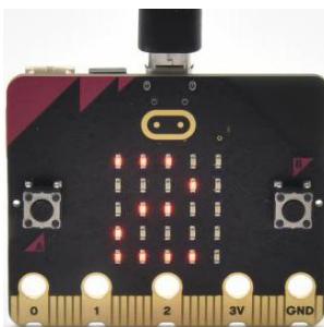
Step 1: connect the Micro: Bit main board V2 with your computer
Firstly, link the Micro: Bit main board V2 with your computer via the USB cable.

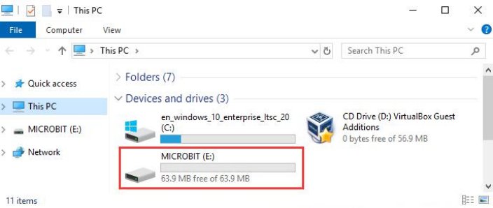
Step 2: if the red LED on the back of the board is on, that means the board is powered. Then Micro: Bit main board V2 will appear on your computer as a driver named ‘MICROBIT’. Please note that it is not an ordinary USB disk as shown below.
Step 3: write programs
https://makecode.microbit.org/

Congratulations on completing your first code! You should now see the 5x5 LED dot matrix displaying various patterns.
Next, I will demonstrate downloading the written code to the computer and uploading it using a different method.

2. CoolTerm Installation
CoolTerm program is used to read the data on serial port.
Download CoolTerm program:
macOS:
Win:
Linux:
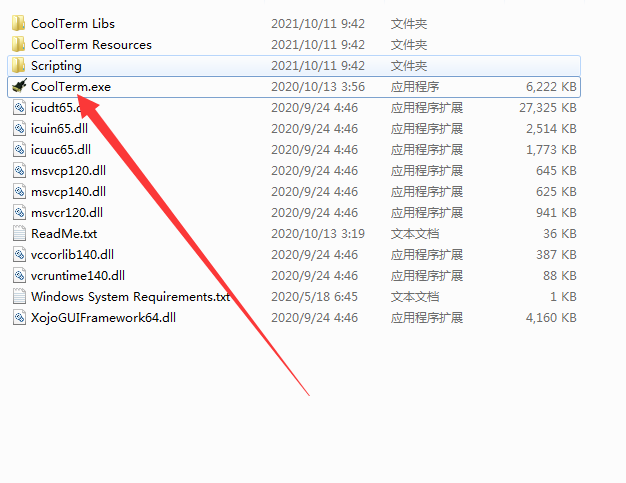
(1) After the download, we need to install CoolTerm program file, below is Window system taken as an example.
(2) Choose “win” to download the zip file of CoolTerm
(3) Unzip file and open it. (also suitable for Mac and Linux system)

The functions of each button on the Toolbar are listed below:
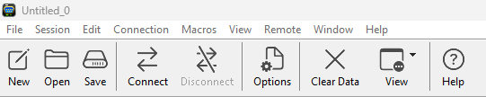
Command |
Description |
|---|---|
New |
Opens up a new Terminal |
Open |
Opens a saved Connection |
Save |
Saves the current Connection to disk |
Connect |
Opens the Serial Connection |
Disconnect |
Closes the Serial Connection |
Clear Data |
Clears the Received Data |
Options |
Opens the Connection Options Dialog |
HEX |
Displays the Terminal Data in Hexadecimal Format |
View |
Displays the Help Window |
After installation is complete, we will use this tool in our subsequent lessons.
3.Makecode Extension Libraries
We have made a makecode extension library for this Mecanum robot car V2.0
Add an extension library of the Mecanum robot car V2.0
Please follow the following steps to add extension files:
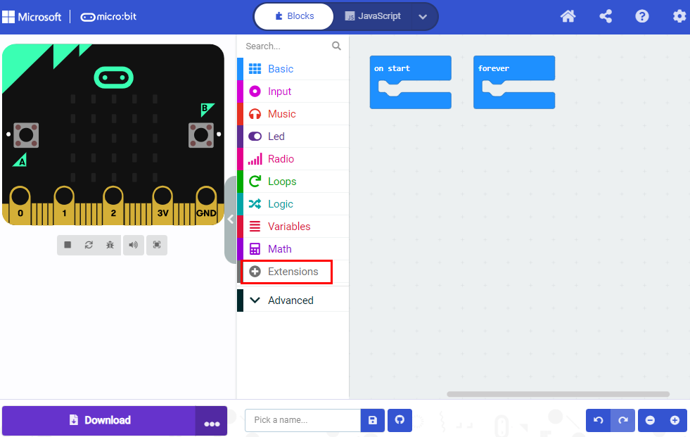
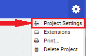
Open Makecode to enter a certain project → click the gear-shaped icon(for setting) in the upper right corner → choose“Extensions”;
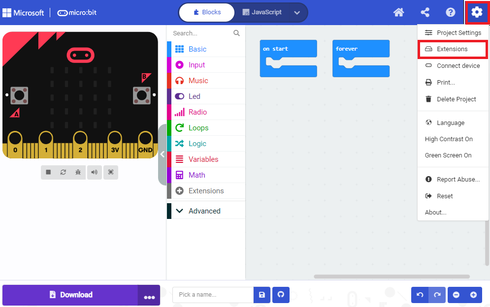
Or click“Extensions”, as shown below:
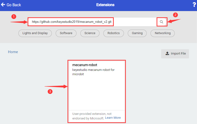
Input the link:
https://github.com/keyestudio2019/mecanum_robot_v2
Tap the searching result “MecanumRobotV2” to download and install it, This process may take a few seconds.
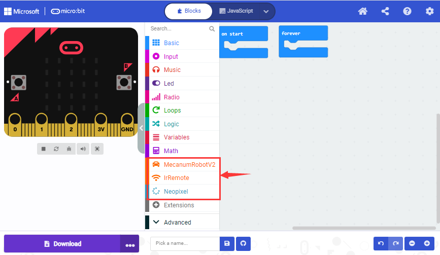
After the installation, you can find the extension files Mecanum RobotV2 and IrRemote on the left side.
And extension file Neopixel is also installed.
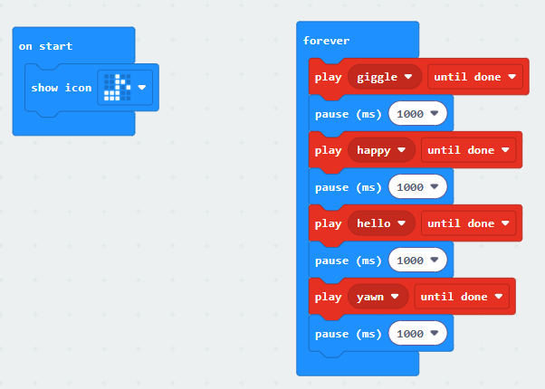
Project 1: Heartbeat
Click to download the code for this lesson
(1)Project Description
(1) Project DescriptionThis project is easy to conduct with a micro:bit V2 main board, a Micro USB cable and a computer. The micro:bit LED dot matrix will display a relatively big heart-shaped pattern and then a smaller one. This alternative change of this pattern is like heart beating. This experiment serves as a starter for your entry to the programming world.
(2)Components Needed:
Micro:bit main board V2
Micro USB cable
(3)Test Code:
Attach the Micro:bit main board V2 to your computer via the Micro USB cable and begin editing.

Complete Program :
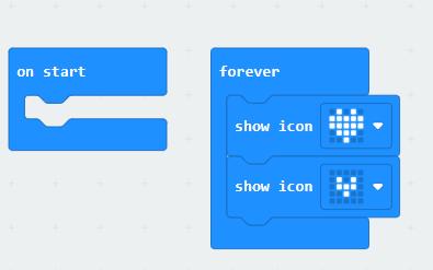
Note: the “on start” means that the code in this block only executes once, while “forever” implies that the code runs cyclically.
(4)Test Results:
After uploading the code, you will see a heartbeat effect appear on the Microbit board.

Project 2: Light A Single LED
Click to download the code for this lesson
(1)Project Description:
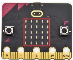
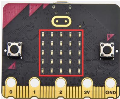
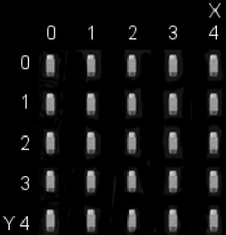
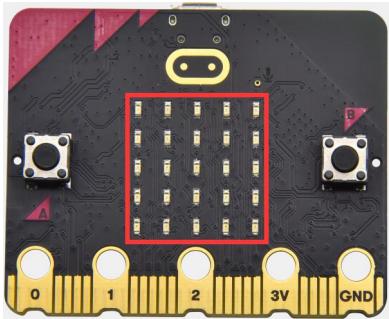
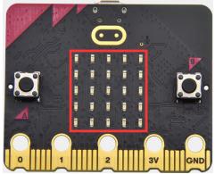
(1)Project Description:The LED dot matrix consists of 25 LEDs arranged in a 5 by 5 square. In order to locate these LEDs quickly, as the figure shown below, we can regarded this matrix as a coordinate system and create two aces by marking those in rows from 0 to 4 from top to bottom, and the ones in columns from 0 to 4 from the left to the right. Therefore, the LED sat in the second of the first line is (1,0) and the LED positioned in the fifth of the fourth column is (3,4) and others likewise.
(2)Components Needed:
Micro:bit main board V2
Micro USB cable
(3)Test Code:
Attach the Micro:bit main board V2 to your computer via the Micro USB cable and begin editing.

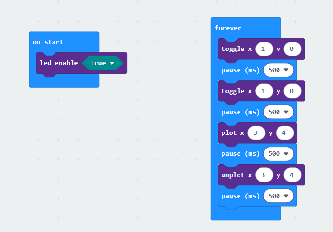
Complete Program :
(4)Test Results
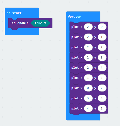
After uploading the code, you will observe the Microbit board display the following effect: (1,0) lights up for 0.5 seconds before turning off, followed by (3,4) lighting up for 0.5 seconds before turning off, repeating in a loop.

Project 3: LED Dot Matrix
Click to download the code 1 for this lesson
Click to download the code 2 for this lesson
(1)Project Description:
Dot matrices are very commonplace in daily life. They have found wild applications in LED advertisement screens, elevator floor display, bus stop announcement and so on.
The LED dot matrix of Micro: Bit main board V2 contains 25 LEDs in a grid. Previously, we have succeeded in controlling a certain LED to light by integrating its position value into the test code. Supported by the same theory, we can turn on many LEDs at the same time to showcase patterns, digits and characters.
What’s more, we can also click” show icon “ to choose the pattern we like to display. Last but not the least, we can design our patterns by ourselves.
(2)Components Needed:
Micro:bit main board V2
Micro USB cable
(3)Test Code 1:
Link computer with micro:bit board by micro USB cable, and program in MakeCode editor.

Complete Program :
(4) Test Results 1:
Upload code 1 and power the board, we will see the icon.

(5) Test Code 2:
Link computer with micro:bit board by micro USB cable, and program in MakeCode editor.

Complete Program :
(6)Test Results 2 :
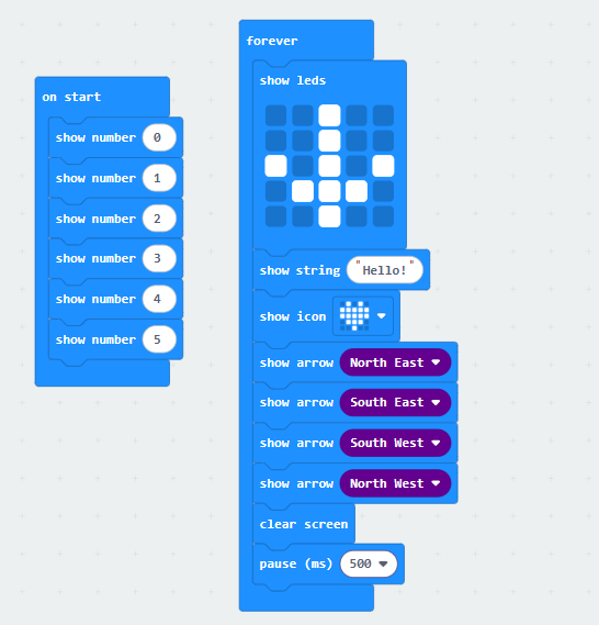
After uploading the code to the Microbit, you can see the 5x5 dot matrix display cycling through the patterns and text specified in the code.(Note: the “on start” means that the code in this block only executes once, while “forever” implies that the code runs cyclically.)

Project 4: Programmable Buttons
Click to download the code 1 for this lesson
Click to download the code 2 for this lesson
(1)Project Description:
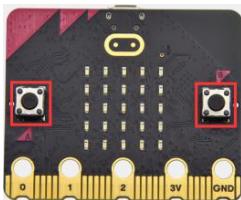
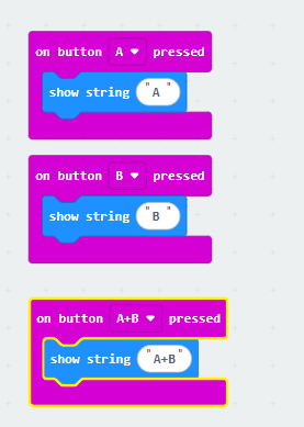
Buttons can be used to control circuits. In an integrated circuit with a button, the circuit is connected when pressing the button and it is open the other way around. Micro: Bit main board V2 boasts three buttons, two are programmable buttons(marked with A and B), and the one on the other side is a reset button. By pressing the two programmable buttons can input three different signals. We can press button A or B alone or press them together and the LED dot matrix shows A,B and AB respectively. Let’s get started.
(2)Components Needed:
Micro:bit main board V2
Micro USB cable
(3)Test Code 1 :
Link computer with micro:bit board by micro USB cable, and program in MakeCode editor,

Complete Code:
(4)Test Results 1 :
After uploading test code 1 to micro:bit main board V2 , the 5*5 LED dot matrix shows A if button A is pressed, B if button B pressed, and AB if button A and B pressed together.

(5) Test Code 2 :

Complete Program :
(6)Test Results 2:
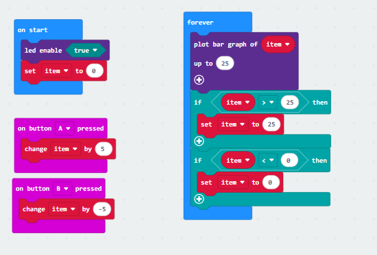
After uploading test code 2 to micro:bit main board V2, when pressing the button A the LEDs turning red increase while when pressing the button B the LEDs turning red reduce.

Project 5: Temperature Detection
Click to download the code 1 for this lesson
Click to download the code 2 for this lesson
(1)Project Description:
The Micro:bit main board V2 is not equipped with a temperature sensor, but uses the temperature sensor built into NFR52833 chip for temperature detection. Therefore, the detected temperature is more closer to the temperature of the chip, and there maybe deviation from the ambient temperature.
(2)Components Needed:
Micro:bit main board V2
Micro USB cable
(3)Test Code 1 :

(4)Test Results 1:
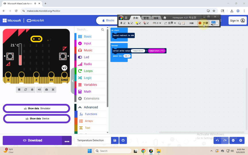
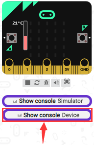
After uploading test code 1 to micro:bit main board V2, powering the main board via the USB cable, and clicking “Show console Device”, the data of temperature shows in the serial monitor page as shown below.
If you’re running Windows 7 or 8 instead of Windows 10, via
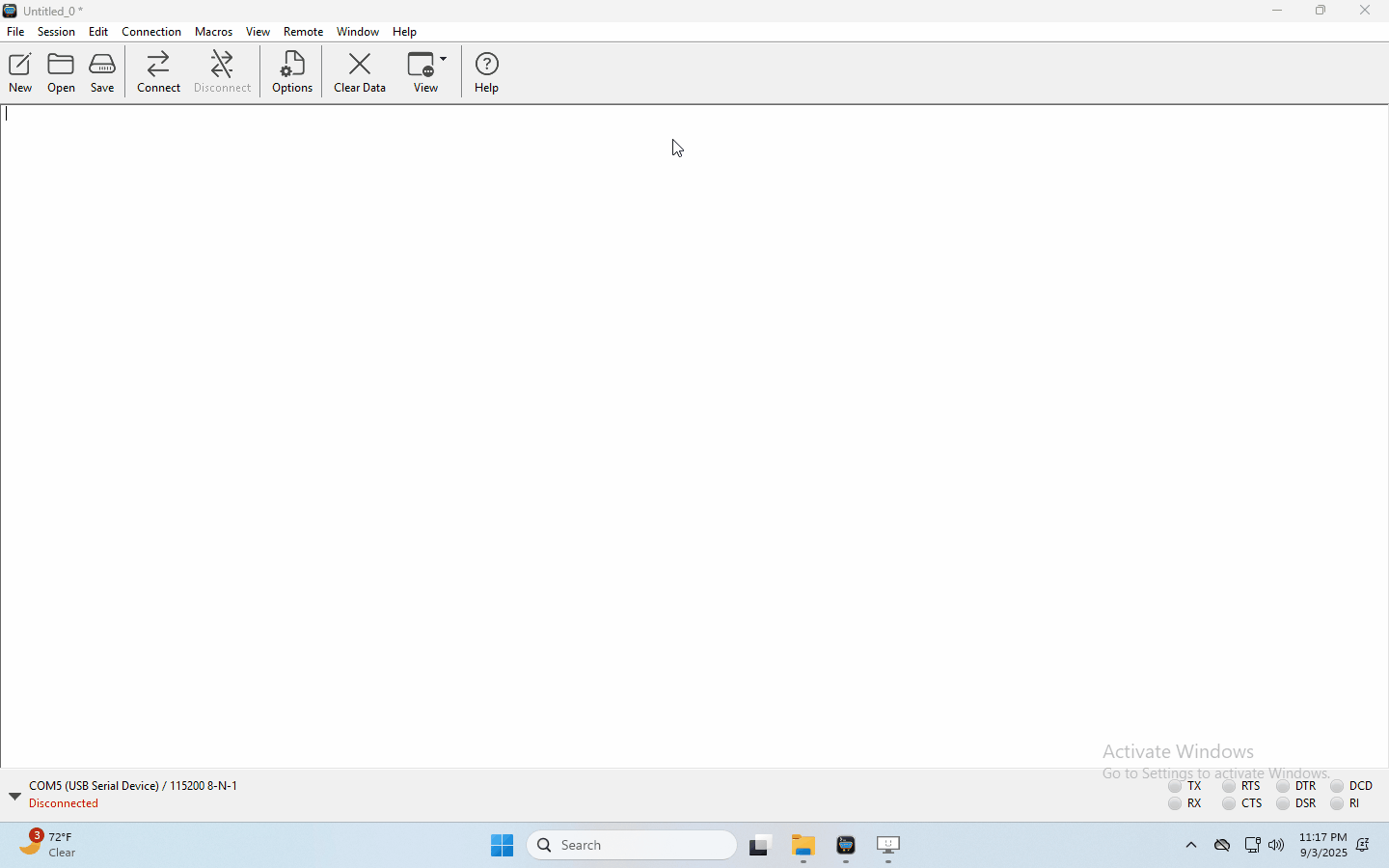
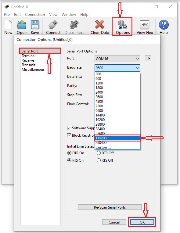
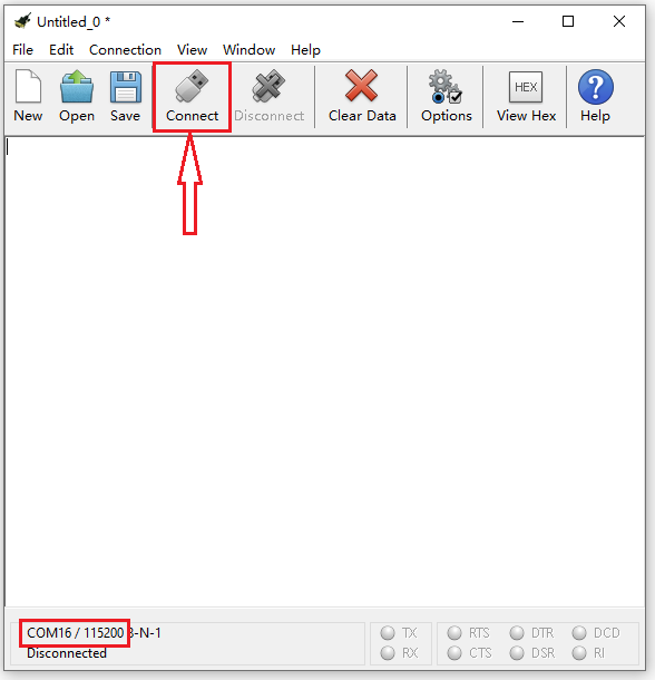
Google Chrome won’t be able to match devices. You’ll need to use the CoolTerm serial monitor software to read data.You could open CoolTerm software, click Options, select SerialPort, set COM port and put baud rate to 115200 (after testing, the baud rate of USB SerialPort communication on Micro: Bit main board V2 is 115200), click OK, and Connect. The CoolTerm serial monitor shows the change of temperature in the current environment, as shown in the figures below :
(5)Test Code 2 :
Link computer with micro:bit board by micro USB cable, and program in MakeCode editor,

Complete Program :
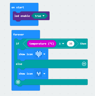
(6)Test Results 2:
After uploading the code 2, when the ambient temperature is less than 35℃, the 5*5 LED dot matrix shows 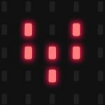 . When the temperature is equivalent to or greater than 35℃, the pattern
  appears.
Project 6: Geomagnetic Sensor
Click to download the code 1 for this lesson
Click to download the code 2 for this lesson
(1)Project Description:
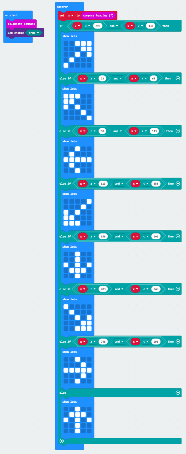
(1) Project Description:This project aims to explain the use of the Micro: bit geomagnetic sensor, which can not only detect the strength of the geomagnetic field, but also be used as a compass to find bearings. It is also an important part of the Attitude and Heading Reference System (AHRS). Micro: Bit main board V2 uses LSM303AGR geomagnetic sensor, and the dynamic range of magnetic field is ± 50 gauss. In the board, the magnetometer module is used in both magnetic detection and compass. In this experiment, the compass will be introduced first, and then the original data of the magnetometer will be checked. The main component of a common compass is a magnetic needle, which can be rotated by the geomagnetic field and point toward the geomagnetic North Pole (which is near the geographic South Pole) to determine direction.
(2)Components Needed:
Micro:bit main board V2
Micro USB cable
(3)Test Code 1 :
Link computer with micro:bit board by micro USB cable, and program in MakeCode editor.

Complete Program :
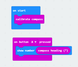
(4)Test Results 1 :
After uploading test code to micro:bit main board V2 and powering the board via the USB cable, and pressing the button A, the board asks us to calibrate compass and the LED dot matrix shows “TILT TO FILL SCREEN”. Then enter the calibration page. Rotate the board until all 25 LEDs are on red as shown below.
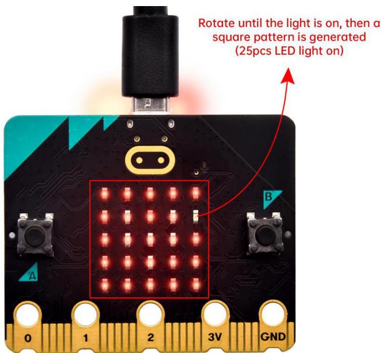
calibrate compass:

After that, a smile pattern  appears, which implies the calibration is done. When the calibration process is completed, pressing the button A will make the magnetometer reading display directly on the screen. And the direction north, east, south and west correspond to 0°, 90°, 180° and 270° respectively.

(5) Test Code 2:
This module can keep reading data to determine direction, so does point to the current magnetic North Pole by arrow.
Link computer with micro:bit board by micro USB cable, and program in MakeCode editor,

Complete Program :
(6) Test Results 2
Upload code 2. After calibration, tilt micro:bit board, and the LED dot matrix displays the direction signs.

Project 7: Accelerometer
Click to download the code 1 for this lesson
Click to download the code 2 for this lesson
(1)Project Description:
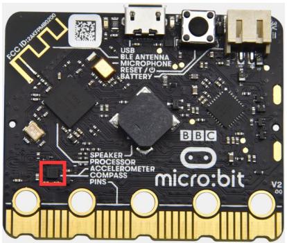
The Micro: Bit main board V2 has a built- in LSM303AGR gravity acceleration sensor, also known as accelerometer, with a resolution of 8/10/12 bits. The code section sets the range to 1g, 2g, 4g, and 8g.
We often use accelerometer to detect the status of machines. In this project, we will introduce how to measure the position of the board with the accelerometer. And then have a look at the original three- axis data output by the accelerometer.
(2)Components Needed:
Micro:bit main board V2
Micro USB cable
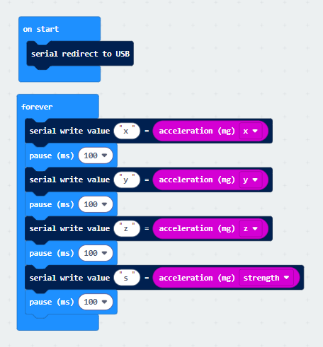
(3)Test Code 1 :
Link computer with micro:bit board by micro USB cable, and program in MakeCode editor,

Complete Program :
(4)Test Results 1:
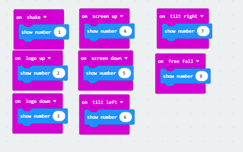
After uploading Test Code 1 to the micro:bit V2 board, changing the board’s orientation will cause the 5x5 dot matrix to display different numbers.

if we shake the Micro: Bit main board V2. no matter at any direction, the LED dot matrix displays the digit “1”.
When it is kept upright ( make its logo above the LED dot matrix), the number 2 shows.
When it is kept upside down( make its logo below the LED dot matrix), it shows as below.
When it is placed still on the desk, showing its front side, the number 4 appears.
When it is placed still on the desk, showing its back side, the number 5 exhibits.
When the board is tilted to the left, the LED dot matrix shows the number 6 as shown below.
When the board is tilted to the right, the LED dot matrix displays the number 7 as shown below
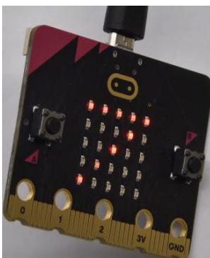
When the board is knocked to the floor, this process can be considered as a free fall and the LED dot matrix shows the number 8. (please note that this test is not recommended for it may damage the main board.)
Attention: if you’d like to try this function, you can also set the acceleration to 3g, 6g or 8g. But still, we do not recommend.
(5)Test Code 2 :

Complete Program :
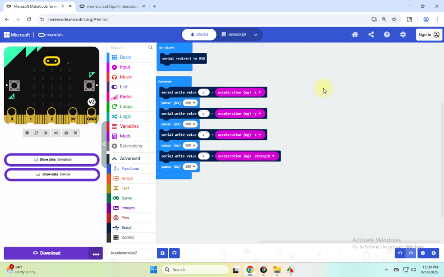
(6) Test Results 2
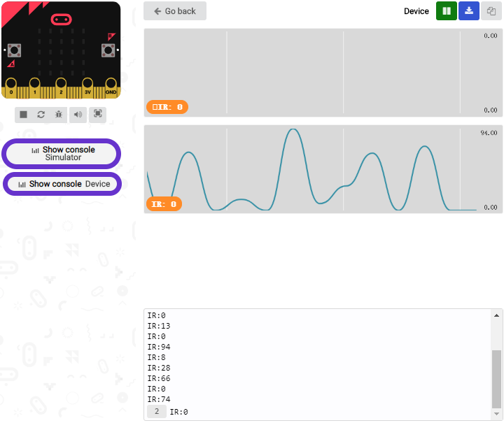
Upload test code to micro:bit main board V2, power the main board via the USB cable, and click “Show console Device”.
The following interface shows the decomposition value of acceleration in X axis, Y axis and Z axis respectively, as well as acceleration synthesis (acceleration synthesis of gravity and other external forces).
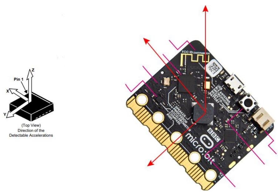
After referring to the MMA8653FC data manual and the hardware schematic diagram of the Micro: Bit main board V2, the accelerometer coordinate of the Micro: Bit V2 motherboard are shown in the figure below:
If you’re running Windows 7 or 8 instead of Windows 10, via Google Chrome won’t be able to match devices. You’ll need to use the CoolTerm serial monitor software to read data.You could open CoolTerm software, click Options, select SerialPort, set COM port and put baud rate to 115200 (after testing, the baud rate of USB SerialPort communication on Micro: Bit main board V2 is 115200), click OK, and Connect. The CoolTerm serial monitor shows the data of X axis, Y axis and Z axis, as shown in the figures below:
Project 8: Light Detection
Click to download the code for this lesson
(1) Project Description:
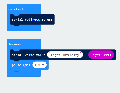
In this project, we focus on the light detection function of the Micro: Bit main board V2. It is achieved by the LED dot matrix since the main board is not equipped with a photoresistor.
(2)Components Needed:
Micro:bit main board V2
Micro USB cable
(3)Test Code:
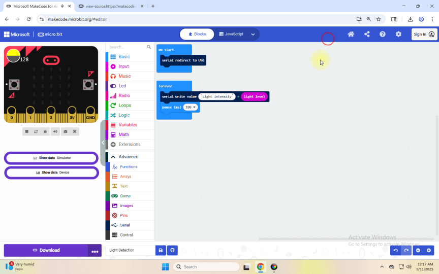
Link computer with micro:bit board by micro USB cable, and program in MakeCode editor,

Complete Program :
(4)Test Results:
Upload the test code to micro:bit main board V2, power the board via the USB cable and click “Show console Device”.
When the LED dot matrix is covered by hand, the light intensity showed is approximately 0; when the LED dot matrix is exposed to light, the light intensity displayed gets stronger with the light as shown below.
If you’re running Windows 7 or 8 instead of Windows 10, via Google Chrome won’t be able to match devices. You’ll need to use the CoolTerm serial monitor software to read data.
You could open CoolTerm software, click Options, select SerialPort, set COM port and put baud rate to 115200 (after testing, the baud rate of USB SerialPort communication on Micro: Bit main board V2 is 115200), click OK, and Connect. The CoolTerm serial monitor shows the value of light intensity, as shown in the figures below :
Project 9: Speaker
Click to download the code for this lesson
(1)Project Description:
The Micro: Bit main board V2 has an built- in speaker, which makes adding sound to the programs easier. We can program the speaker to air all kinds of tones, like playing the son Ode to Joy.
(2)Components Needed:
Micro:bit main board V2
Micro USB cable
(3)Test Code :
Link computer with micro:bit board by micro USB cable, and program in MakeCode editor,

Complete Program :
(4)Test Results:
After uploading the test code to micro:bit main board V2 and powering the board via the USB cable, the speaker utters sound and the LED dot matrix shows the logo of music.

Project 10: Touch-sensitive Logo
Click to download the code for this lesson
(1)Project Description:
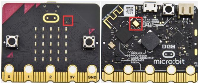
The Micro: Bit main board V2 is equipped with a golden touch- sensitive logo, which can act as an input component and function like an extra button.
It contains a capacitive touch sensor that senses small changes in the electric field when pressed (or touched), just like your phone or tablet screen do.When you press it , you can activate the program.
(2)Components Needed:
Micro:bit main board V2
Micro USB cable
(3)Test Code :
Link computer with micro:bit board by micro USB cable, and program in MakeCode editor,

Complete Program :
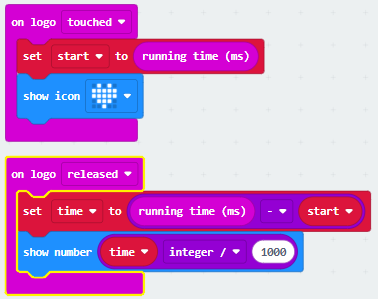
(4)Test Results:
After uploading the code, touching the logo with your hand will display a heart shape on the dot matrix. Releasing your touch will reveal a number, with longer contact times displaying larger numbers.

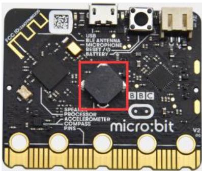
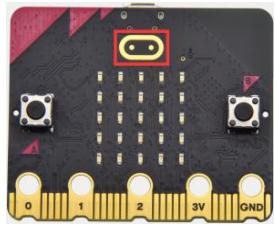
Project 11: Microphone
Click to download the code 1 for this lesson
Click to download the code 2 for this lesson
(1)Project Description:
The Micro: Bit main board V2 is built with a microphone which can test the volume of ambient environment. When you clap, the microphone LED indicator turns on. Since it can measure the intensity of sound, you can make a noise scale or disco lighting changing with music. The microphone is placed on the opposite side of the microphone LED indicator and in proximity with holes that lets sound pass. When the board detects sound, the LED indicator lights up.
(2) Components Needed:
Micro:bit main board V2
Micro USB cable
(3) Test Code 1:
Link computer with micro:bit board by micro USB cable, and program in MakeCode editor,

Complete Program :
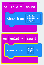
(4)Test Results 1:
After uploading the code, display a large heart icon when ambient sound is detected, and a small heart icon when the surroundings are quiet (Note: Sounds too faint to detect will not trigger the response).

(5)Test Code 2:
Link computer with micro:bit board by micro USB cable, and program in MakeCode editor,

Complete Program :
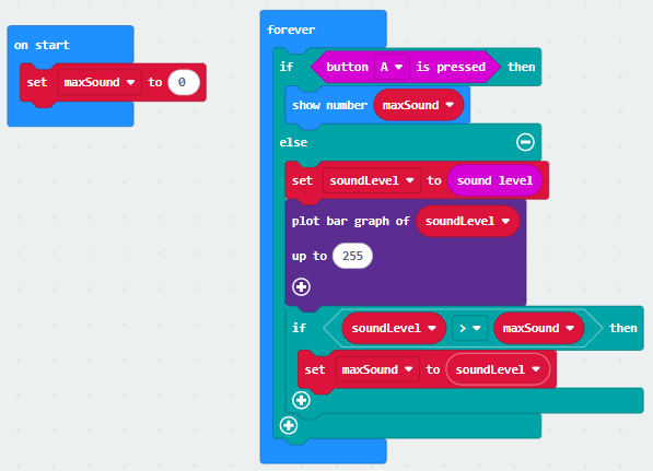
(6)Test Results 2:

After uploading the code, the dot matrix pulses in sync with sound changes. Pressing the “A” key displays the numerical value of the current sound.
Project 12: Bluetooth Wireless Communication

(1)Project Description:
Note: This lesson focuses on explaining how to upload code via Bluetooth using an app, so no code is provided. Please follow the steps in the animated gif.
The Micro: Bit main board V2 comes with a nRF52833 processor (with a built- in BLE(Bluetooth Low Energy) device Bluetooth 5.1 ) and a 2.4GHz antenna for Bluetooth wireless communication and 2.4GHz wireless communication. With the help of them, the board is able to communicate with a variety of Bluetooth devices, including smart phones and tablets.
In this project, we mainly concentrate on the Bluetooth wireless communication function of this main board. Linked with Bluetooth, it can transmit code or signals. To this end, we should connect an Apple device (a phone or an iPad) to the board.
Since setting up Android phones to achieve wireless
transmission is similar to that of Apple devices, no need to illustrate again.
(2) Preparation
Attachment of Micro:bit main board V2 to your computer via the Micro USB cable.
An Apple device (a phone or an iPad) or an Android device;
(3) Install Micro:bit:
For Android

For ios

(4)Test Code :
Next, we’ll use our phones to write code and connect via Bluetooth (Note: The process is identical for both Android and iOS devices; this demonstration uses an Android phone).
1、Open the software and connect to Bluetooth.

2、Press Microbit’s button A, button B, and the reset button on the back in sequence. The main board will then display an icon.

3、Enter the pattern displayed in step two into the phone interface.

Write code and upload
1、Enter the code programming interface and write a code.

2、Press button A, button B, and the reset button in sequence. (Note: This procedure must be repeated each time code is uploaded via the app.)

3、After confirming that the Microbit icon matches the one displayed on your phone, simply click “Next.”

Finally, you can see the Microbit board displaying the pattern from the code.
Here, we have completed the process of uploading code to the phone. It is important to note:
To connect the phone to the Microbit board, press the A, B, and Reset buttons in sequence. The dot matrix display will then show a pattern, which should be entered into the phone.
The Microbit board can be powered via a USB cable or by supplying 3V to the board’s power input through a battery pack. Note: The voltage must not exceed 3V, as exceeding this limit will damage the board.
Project 13:Seven-Color LED
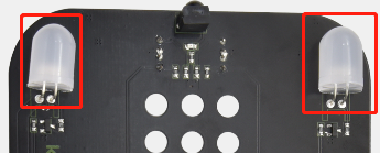
(1) Description
This module consists of a commonly used LED with 7colors but in white appearance. It can automatically flash different colors to create fantastic light effects when high level is input like a normal LED.
(2) Preparation
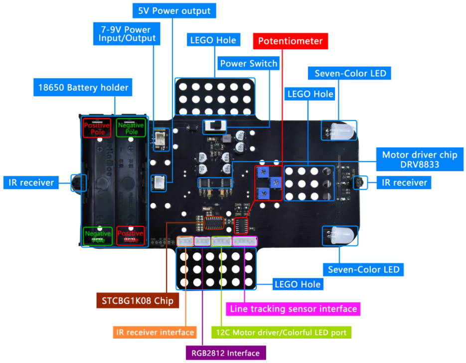
Insert the micro:bit board into the slot of keyestudio 4WD Mecanum Robot Car V2.0
Place batteries into battery holder
Dial power switch to ON end
Connect the micro:bit to your computer via an USB cable
Open the Web version of Makecode.
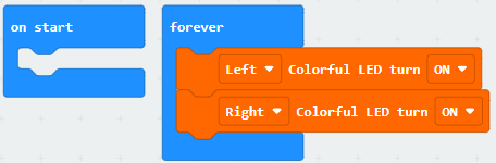
(3) Test Code1
Make the RGB light flash 7 lights alternatively.
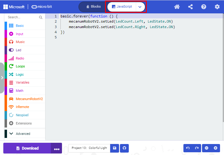
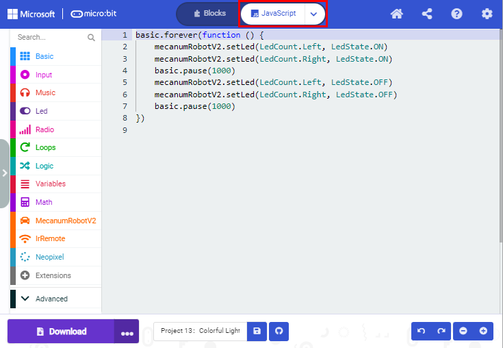
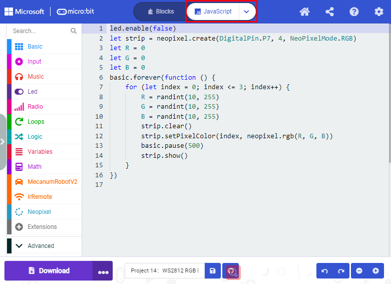
Click“JavaScript”to view the corresponding JavaScript code:
(4) Test Result1
Download code 1 to micro:bit board and dial POWER switch to ON end, 2 RGB lights of smart car emit red, green, blue, indigo, dark red, yellow and white color cyclically.
(5) Test Code2
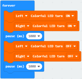
Click“JavaScript”to view the corresponding JavaScript code:
(6) Test Result2
Download code 2 to micro:bit board, 2 RGB lights will flash for 1 second and then stop flashing for 1 second, cyclically.
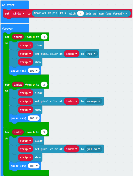
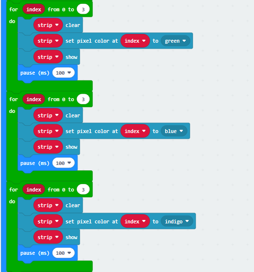
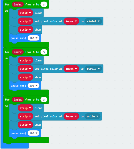
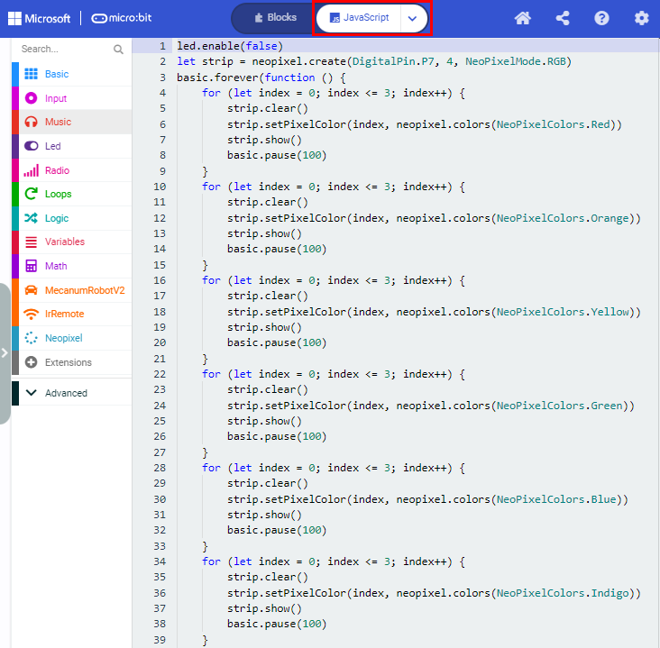
Project 14:4 WS2812 RGB LEDs
(1) Description
The driver shield cooperates 4 pcs WS2812 RGB LEDs, compatible with micro:bit board and controlled by P7. In this lesson, we will make the RGB LEDs display different colors by P7. In this lesson, 3 sets of test code are provided to make the 4 WS2812 RGB LEDs display different effects.
(2) Preparation
Insert the micro:bit board into the slot of keyestudio 4WD Mecanum Robot Car V2.0
Place batteries into battery holder
Dial power switch to ON end
Connect the micro:bit to your computer via an USB cable
Open the Web version of Makecode.
(3) Test Code1
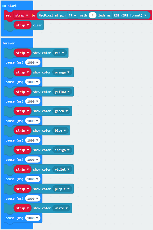
Click“JavaScript” to switch into the corresponding JavaScript code:
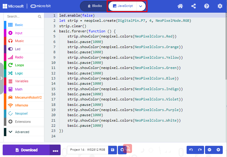
(4) Test Result1
Download code 1 to micro:bit, and dial POWER to ON end. All four WS2812RGB LEDs light up a different color a time cyclically.
(5) Test Code2
Click“JavaScript” to switch into the corresponding JavaScript code:
(6) Test Result2
Download code 2 to micro:bit, WS2812RGB LEDs display like flow light.
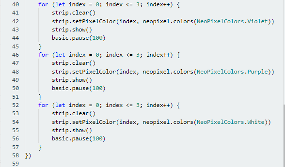
(7) Test Code3
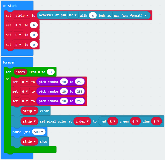
Click“JavaScript”to switch into the corresponding JavaScript code:
(8) Test Result3
Download code 3 to micro:bit, every WS2812RGB light shows random color one by one.
Project 15:Servo
(1) Description
For those DIY smart cars, they often have the function of automatic obstacle avoidance. In the DIY process, we need to use a servo to control the ultrasonic module to rotate left and right, and then detect the distance between the car and the obstacle, so as to control the car to avoid the obstacle. If other microcontrollers are used to control the rotation of the servo, we need to set a certain frequency and a certain width of pulse to control the servo angle.
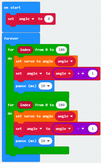
However, if the micro:bit main board is used to control the servo angle, we only need to set the control angle in the development environment where the corresponding pulse will be automatically set to control the servo rotation. In this project, you will learn how to control the servo to rotate back and forth between 0° and 90°.
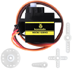
(2) Information of the Servo
Servo motor is a position control rotary actuator. It mainly consists of housing, circuit board, core-less motor, gear and position sensor. Its working principle is that the servo receives the signal sent by MCU or receiver, and produces a reference signal with a period of 20ms and width of 1.5ms, then compares the acquired DC bias voltage to the voltage of the potentiometer and obtains the voltage difference output.
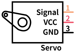
For the servo used in this project, the brown wire is the ground, the red one is the positive wire, and the orange one is the signal wire.
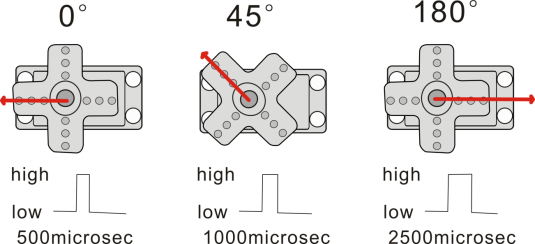
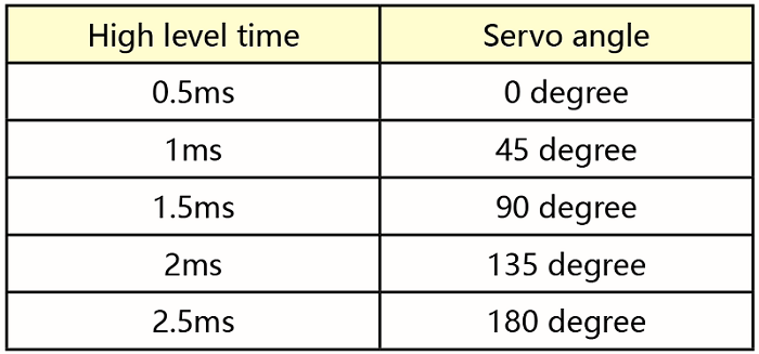
The rotation angle of servo motor is controlled by regulating the duty cycle of PWM (Pulse-Width Modulation) signal. The standard cycle of PWM signal is 20ms (50Hz). Theoretically, the width is distributed between 1ms-2ms, but in fact, it’s between 0.5ms-2.5ms. The width corresponds to the rotation angle from 0° to 180°. But note that for different brand motor, the same signal may have different rotation angle.
More details:
(3) Parameters
Working voltage: DC 4.8V ~ 6V
Operating angle range: about 180 ° (at 500 → 2500 μsec)
Pulse width range: 500 → 2500 μsec
No-load speed: 0.12 ± 0.01 sec / 60 (DC 4.8V) 0.1 ± 0.01 sec / 60 (DC 6V)
No-load current: 200 ± 20mA (DC 4.8V) 220 ± 20mA (DC 6V)
Stopping torque: 1.3 ± 0.01kg · cm (DC 4.8V) 1.5 ± 0.1kg · cm (DC 6V)
Stop current: ≦ 850mA (DC 4.8V) ≦ 1000mA (DC 6V)
Standby current: 3 ± 1mA (DC 4.8V) 4 ± 1mA (DC 6V)
(4) Preparation
Insert the micro:bit board into the slot of keyestudio 4WD Mecanum Robot Car V2.0
Place batteries into battery holder
Dial power switch to ON end
Connect the micro:bit to your computer via an USB cable
Open the Web version of Makecode
(5) Test Code
Click“JavaScript” to view the corresponding JavaScript code:
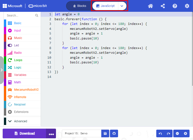
(6) Test Result
After uploading the test code and dial POWER switch to ON end, the servo rotates from 0 degree to 180 degrees.
Project 16:Motor
(1) Description
The Keyestudio 4WD Mecanum Robot Car is equipped with 4 DC reduction motors, also called gear reduction motor, which is developed on the ordinary DC motor. It has a matching gear reduction box which provides a lower speed but a larger torque. Furthermore, different reduction ratios of the box can provide different speeds and torques.
Gear motor is the integration of gearmotor and motor, which is applied widely in steel and machine industry
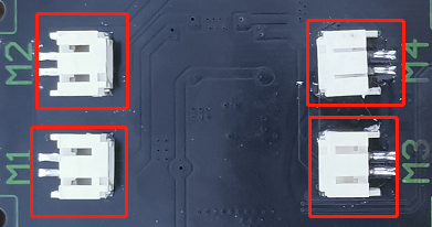
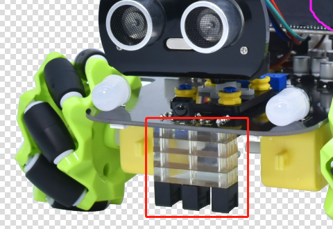
Micro:bit motor driver shield comes with a DRV8833 chip. In order to save the IO port resource, we control the rotation direction and speed of 4 DC gear motors with the DRV8833 chip.
Front
Back
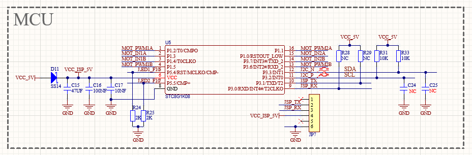
STC8G1K08 Chip circuit
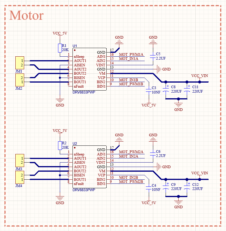
HR8833 Motor driver circuit
(2) Preparation
Insert the micro:bit board into the slot of keyestudio 4WD Mecanum Robot Car V2.0
Place batteries into battery holder
Dial power switch to ON end
Connect the micro:bit to your computer via an USB cable
Open the Web version of Makecode
(3) Test Code1
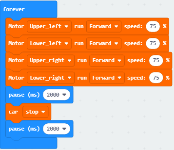
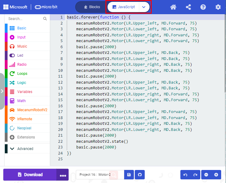
Click“JavaScript” to view the corresponding JavaScript code:
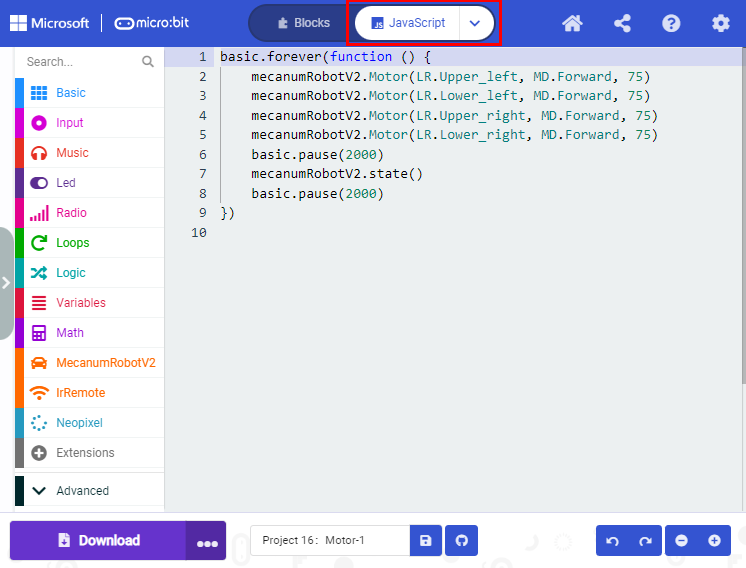
(4) Test Result1
Download code 1 to micro:bit board, dial POWER switch to ON end. Smart car goes forward for 2s and stops for 2s.
(5) Test Code2
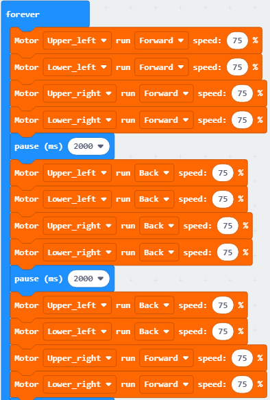
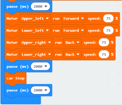
Click“JavaScript” to view the corresponding JavaScript code:
(6) Test Result2
Download code 2 to micro:bit board, the car goes forward for 2s, turns back for 2s, turn left for 2s, turn right for 2s and stops for 2s and repeats this pattern.
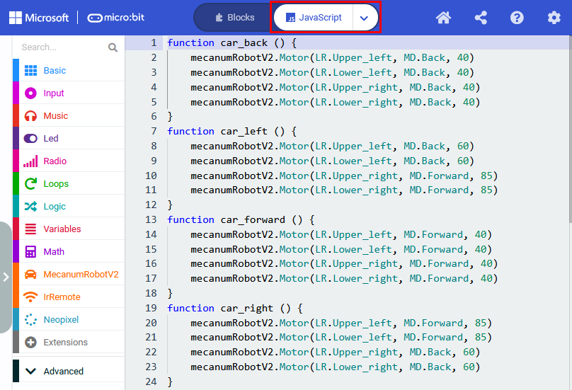
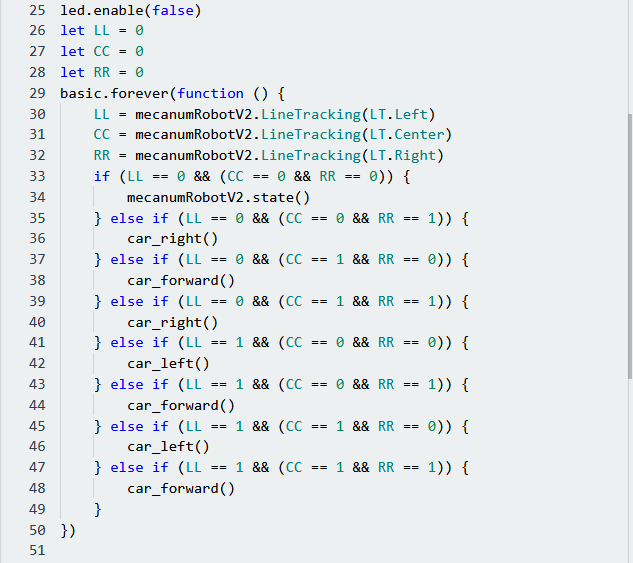
Project 17:Line Tracking Sensor
Project 17.1:Detect Line Tracking Sensor
1. Description
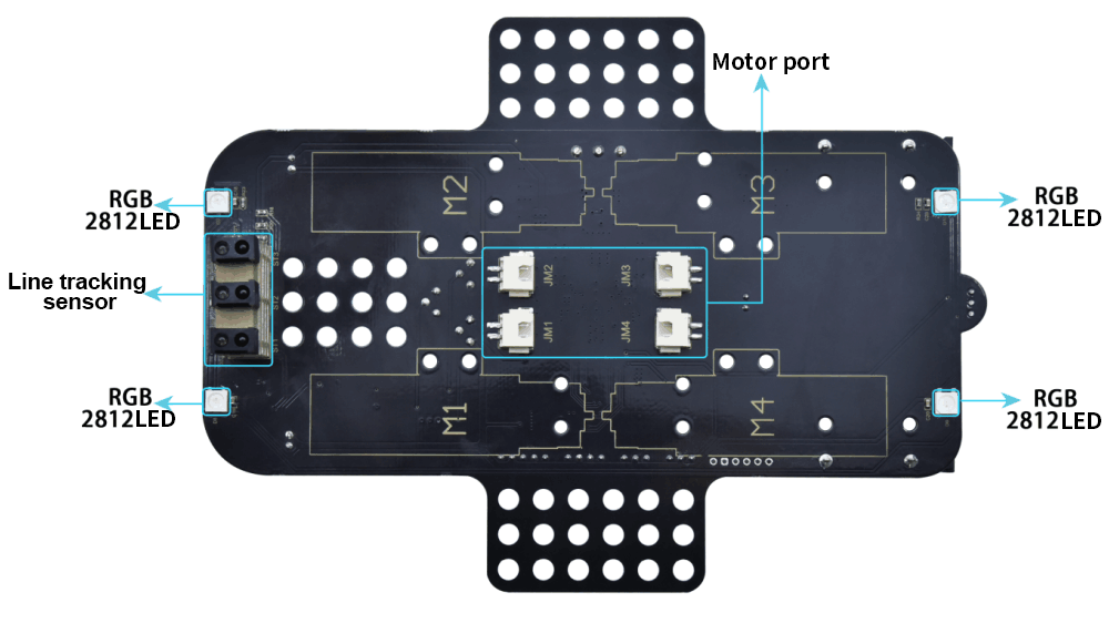
The motor driver board of the Keyestudio 4WD Mecanum Robot Car comes with a 3-channel line tracking sensor, which adopts TCRT5000 IR tubes and 3 potentiometers.
The TCRT5000 IR tube contains an IR emitting tube and an IR receiving tube. When the infrared signals of the emitting tube is received by the receiving tube through reflection, the resistance of the receiving tube will change, which is generally reflected in the voltage change on the circuit.
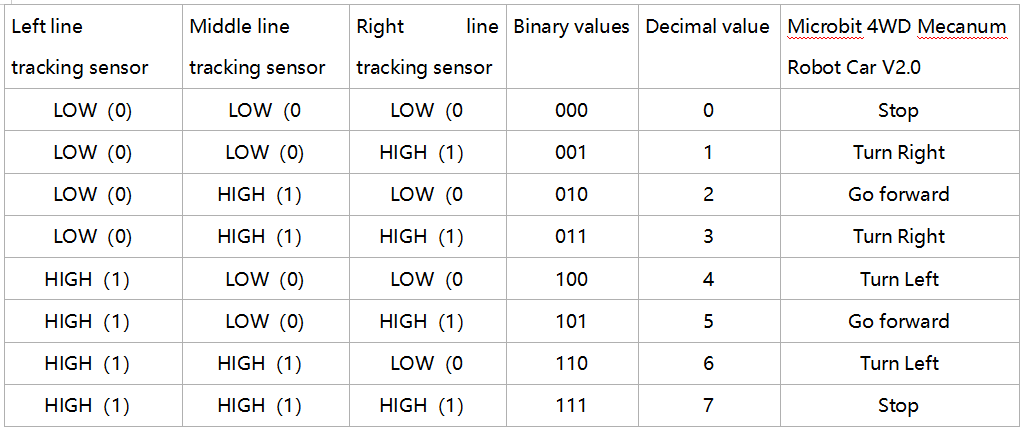
The resistance varies depending on the intensity of the infrared signals received by the receiving tube, which is often in the color of the reflecting surface and the distance of the reflecting surface receiving tube. At the time of detection, black is high level active and white is low level active.
2. Working Principle
When the car runs above a white road, the IR emitting tube installed under the car emits infrared signals to detect the road and the receiving tube will receive signals sending back. Then the output end outputs low level(0); when it detects black lines, it outputs high level(1).
After putting a white paper on the bottom of the 4WD Mecanum Robot Car, we will rotate the potentiometers on the 3-way tracking sensor. When the indicator light on the sensor module is on, pick up the car to make the two wheels on the 4WD Mecanum Robot Car separate. The height of the white paper is about 1.5cm, when the indicator light on the sensor module is off, and then the sensitivity is adjusted.
3. Preparation
Insert the micro:bit board into the slot of keyestudio 4WD Mecanum Robot Car V2.0
Place batteries into battery holder
Dial power switch to ON end
Connect the micro:bit to your computer via an USB cable
Open the Web version of Makecode
4. Test Code
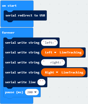
Click“JavaScript” to view the corresponding JavaScript code:
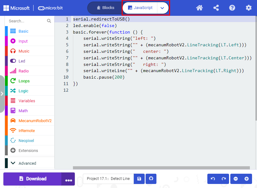
5. Test Result
Download code to micro:bit board, dial POWER switch to ON end.
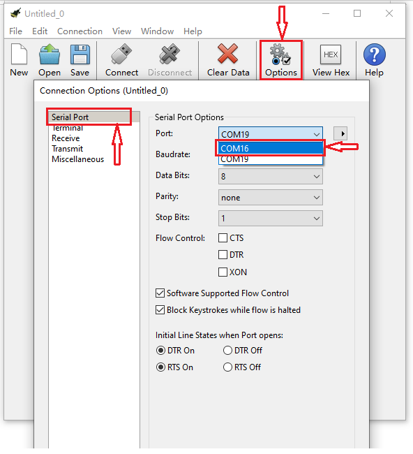
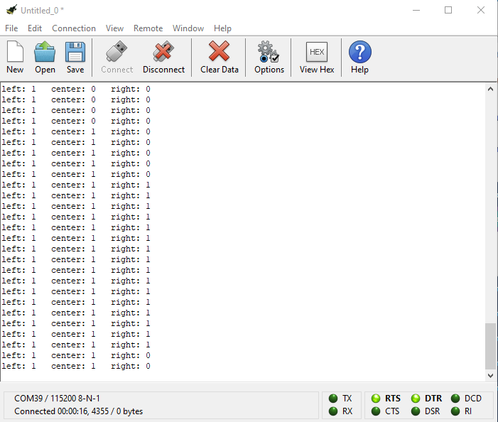
Open CoolTerm, click Options to select SerialPort. Set COM port and 115200 baud rate. Click“OK”and“Connect”.
The CoolTerm serial monitor displays the digital signals read by the line tracking sensors.
Project 17.2:Tracking Smart Car
1. Description
In this lesson we will combine a line tracking sensor with a motor to make a line tracking smart car.
The micro:bit board will analyze the signals and control the smart car to show the line tracking function.
2. Working Principle
The smart car will make different moves according to the value received by the 3-channel line tracking sensor.
3. Preparation
Insert the micro:bit board into the slot of keyestudio 4WD Mecanum Robot Car V2.0
Place batteries into battery holder
Dial power switch to ON end
Connect the micro:bit to your computer via an USB cable
Open the Web version of Makecode
Warning: The 3-way tracking sensor should be used in environments without infrared interference such as sunlight. Sunlight contains a lot of invisible light, such as infrared and ultraviolet. In an environment with strong sunlight, the 3-way tracking sensor cannot work properly.
4.Flow Chart

5. Test Code
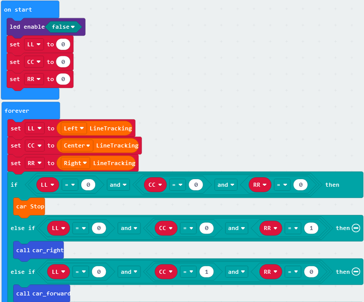

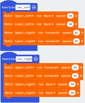
Click“JavaScript”to view the corresponding JavaScript code:
5. Test Result
Download code to micro:bit and dial POWER to ON end, line tacking car goes forward along black line .
Note: turn on the switch at the back of micro:bit car, the width of black line should be larger than the width of line tracking sensor.
Avoid to test smart car under the strong light.
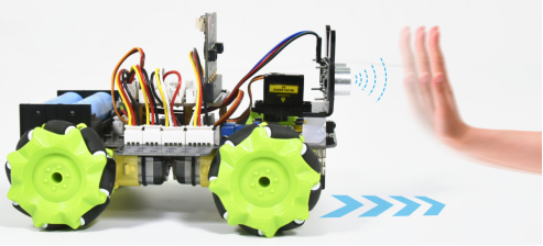
Project 18:Ultrasonic Sensor
Project 18.1:Ultrasonic Ranging
1. Description
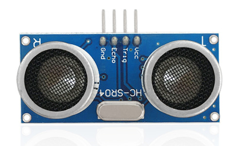
The ultrasonic sensor uses sonar to determine distance to an object like bats do. It offers excellent non-contact range detection with high accuracy and stable readings in an easy-to-use package. It comes complete with ultrasonic transmitter and receiver modules.
The ultrasonic sensor is being used in a wide range of electronics projects for creating obstacle detection and distance measuring application as well as various other applications.
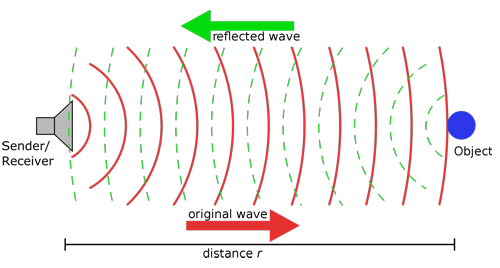
The ultrasonic module will emit the ultrasonic waves after trigger signals. When the ultrasonic waves encounter the object and are reflected back, the module outputs an echo signal, so it can determine the distance of object from the time difference between trigger signal (TRIG)and echo signal(ECHO).
As the picture shows, it is like two eyes. One is transmitting end, the other is receiving end.
According to the above wiring diagram, the integrated port of the ultrasonic sensor module is connected to the 5V G P15 P16 port on the micro:bit motor driver base plate. The Trig (T) pin is controlled by P15 of the micro:bit and the pin of Echo (E) the P16.
2. Working Principle
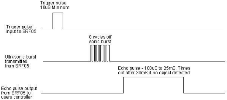
(1)Pull down TRIG then trigger high level signals with least 10us;
(2)After triggering, the module will automatically send eight 40KHz ultrasonic pulses and detect whether there is a signal return;
(3)If there is a signal return, when ECHO (E) outputs a high level, then the duration of the high level is the time from transmission to reception of the ultrasonic waves. Then test distance = high level duration *340m/s*0.5.
3. Parameters
Working voltage: 3-5.5V (DC)
Working current: 15mA
Working frequency: 40khz
Maximum detection distance: about 3m
Minimum detection distance: 2-3cm
Precision: up to 0.2cm
Sensing angle: less than 15 degrees
Input trigger pulse: 10us TTL level
Output echo signal: output TTL level signal (high), proportional to range
4. Preparation
Insert the micro:bit board into the slot of keyestudio 4WD Mecanum Robot Car V2.0
Place batteries into battery holder
Dial power switch to ON end
Connect the micro:bit to your computer via an USB cable
Open the Web version of Makecode
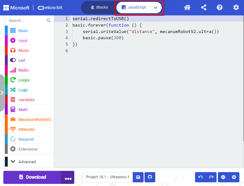
5. Test Code
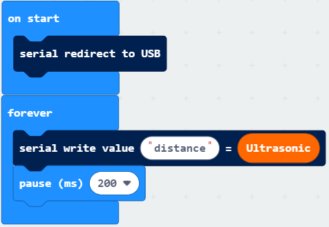
Click“JavaScriptto view the corresponding JavaScript code:
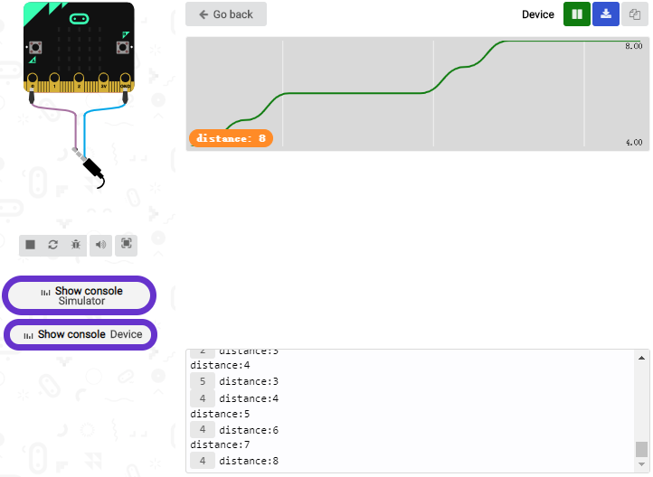
6. Test Result
Download code to micro:bit, keep USB cable connected, dial POWER switch to ON end. The distance value will be displayed on monitor.
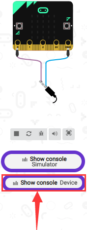
The monitor shows the distance between the obstacle and ultrasonic sensor(as shown below).
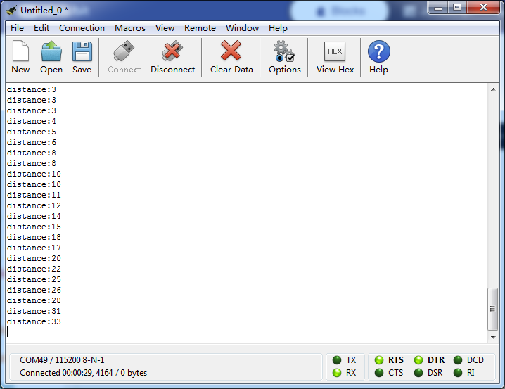
Open CoolTerm, click Options to select SerialPort. Set COM port and 115200 baud rate(the baud rate of USB serial communication of Micro:bit is 115200 through the test). Click “OK” and “Connect”.
CoolTerm serial monitor displays the distance value as follows:
Project 18.2:Ultrasonic Avoidance
1. Description
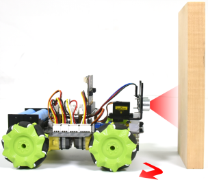
In this project, we will integrate an ultrasonic sensor and a car to make an ultrasonic avoidance car.
Its principle is to detect the distance between the car and obstacle via the ultrasonic sensor to control the motion of smart car.
2. Preparation
Insert the micro:bit board into the slot of keyestudio 4WD Mecanum Robot Car V2.0
Place batteries into battery holder
Dial power switch to ON end
Connect the micro:bit to your computer via an USB cable
Open the Web version of Makecode
3. Flow Chart

4. Test Code

Click“JavaScript”to view the corresponding JavaScript code:

5. Test Result
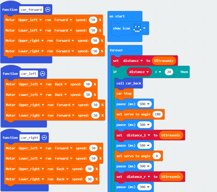
Download code to micro:bit, dial to ON end, and dial POWER to ON end. When the obstacle distance is greater than 20cm, the car goes forward ; on the contrary, smart car turns left.
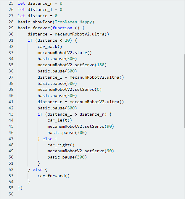
Project 18.3:Ultrasonic Following
1. Description
In previous lesson, we’ve learned the basic principle of line tracking sensor. Next, we will combine the ultrasonic sensor with the car to make an ultrasonic following car.
The ultrasonic sensor detects the obstacle distance and control the motion status of car.
2. Preparation
Insert the micro:bit board into the slot of keyestudio 4WD Mecanum Robot Car V2.0
Place batteries into battery holder
Dial power switch to ON end
Connect the micro:bit to your computer via an USB cable
Open the Web version of Makecode
3. Flow Chart

4. Test Code
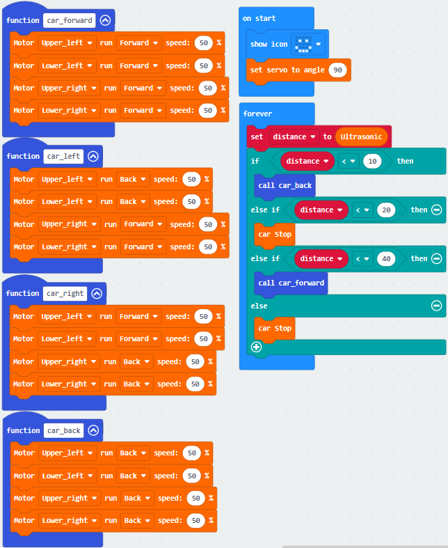
Click“JavaScript”to view the corresponding JavaScript code:
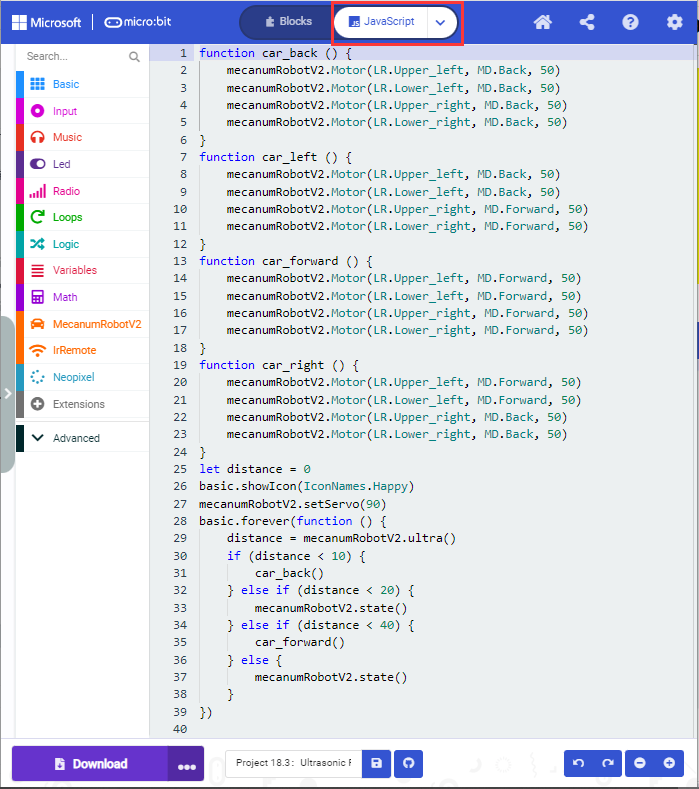
5. Test Result
Download code to micro:bit, dial POWER switch to ON end on shield, smart car could follow the obstacle to move.
Project 19:IR Remote Control
Project 19.1:Decode IR Remote Control
1. Description
There is no doubt that infrared remote control is ubiquitous in daily life. It is used to control various household appliances, such as TVs, stereos, video recorders and satellite signal receivers. Infrared remote control is composed of infrared transmitting and infrared receiving systems, that is, an infrared remote control, an infrared receiving module and a single-chip microcomputer capable of decoding.
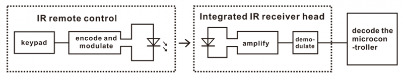
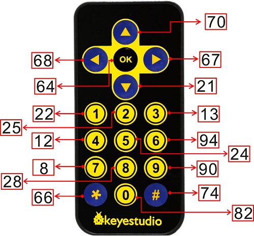
The 38K infrared carrier signal emitted by remote controller is encoded by the encoding chip in the remote controller. It is composed of a section of pilot code, user code, user inverse code, data code, and data inverse code. The time interval of the pulse is used to distinguish whether it is a 0 or 1 signal and the encoding is made up of these 0, 1 signals.
The user code of the same remote control is unchanged. The data code can distinguish the key.
When the remote control button is pressed, the remote control sends out an infrared carrier signal. When the IR receiver receives the signal, the program will decode the carrier signal and determines which key is pressed. The MCU decodes the received 01 signal, thereby judging what key is pressed by the remote control.
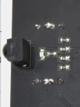
Infrared receiver we use is an infrared receiver module. Mainly composed of an infrared receiver head, it is a device that integrates reception, amplification, and demodulation. Its internal IC has completed demodulation, and can achieve from infrared reception to output and be compatible with TTL signals. Additionally, it is suitable for infrared remote control and infrared data transmission. The infrared receiving module made by the receiver has only three pins, signal line, VCC and GND.
According to the picture above, the integrated port of the infrared receiver is connected to the P9 5V G port on the motor driver board and controlled by the the P9 of the micro:bit.
2. Parameters:
Operating Voltage: 3.3-5V(DC)
Interface: 3PIN
Output Signal: Digital signal
Receiving Angle: 90 degrees
Frequency: 38khz
Receiving Distance: about 5m
3. Preparation
Insert the micro:bit board into the slot of keyestudio 4WD Mecanum Robot Car V2.0
Place batteries into battery holder
Dial power switch to ON end
Connect the micro:bit to your computer via an USB cable
Open the Web version of Makecode
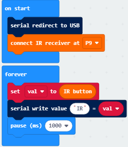
4. Test Code
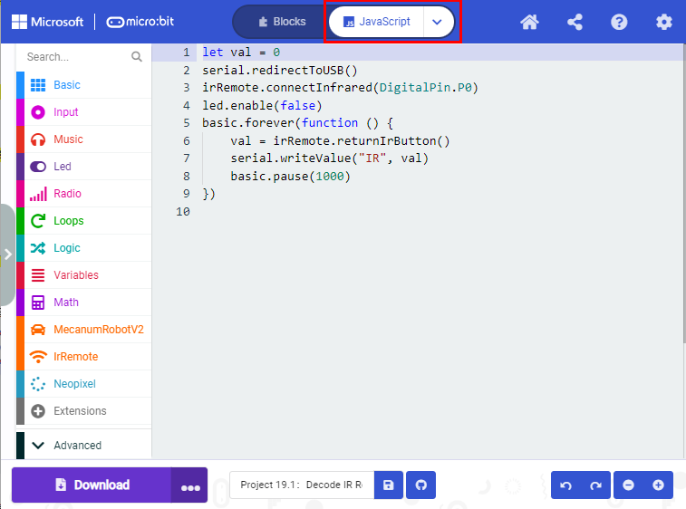
Click“JavaScript” to switch into the corresponding JavaScript code:
Code explanation: If the buttons are not pressed, the serial monitor constantly shows 0; when pressed, the corresponding key values are displayed.
Notes:
The remote control in this kit is not inclusive of batteries. We recommend you to purchase them online.(battery type:CR2025).
Make sure IR remote is good before test. There is a tip for you to check it.
Open the cellphone camera , make IR remote control point at camera and press button. The remote control is good if you see the purple flashing light in the camera.
5. Test Result
Download code to micro: bit board and don’t plug off USB cable Click
Make IR remote control point at IR receiver and press the button, the serial monitor will display the corresponding key values, as shown below:
Open CoolTerm, click Options to select SerialPort. Set COM port and 115200 baud rate. Click“OK”and“Connect”.
CoolTerm serial monitor shows the key value as follows:

The key value is displayed as for your reference:
Project 19.2:IR Remote Control
1. Description
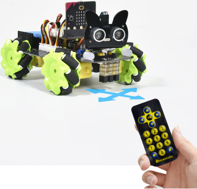
In this project, we combine IR remote control with car shield to make an IR remote smart car. Its principle is to control the motion of car by sending key signals from IR remote control to IR receiving module of car shield.
2. Preparation
Insert the micro:bit board into the slot of keyestudio 4WD Mecanum Robot Car V2.0
Place batteries into battery holder
Dial power switch to ON end
Connect the micro:bit to your computer via an USB cable
Open the Web version of Makecode
Note: The infrared sensor and infrared remote control should not be used in environments with infrared interference such as sunlight for it contains a lot of invisible lights, such as infrared and ultraviolet. In an environment with strong sunlight, they cannot work normally.
3. Flow Chart

4. Test Code
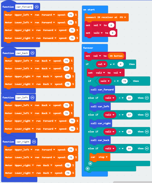
Click“JavaScript” to switch into the corresponding JavaScript code:
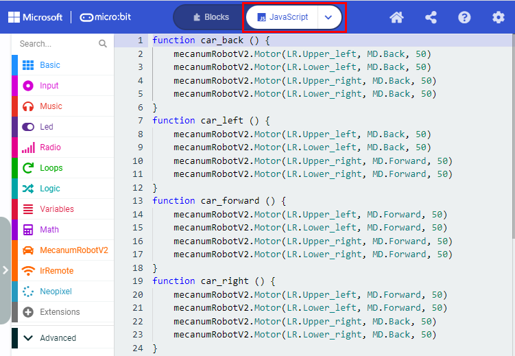
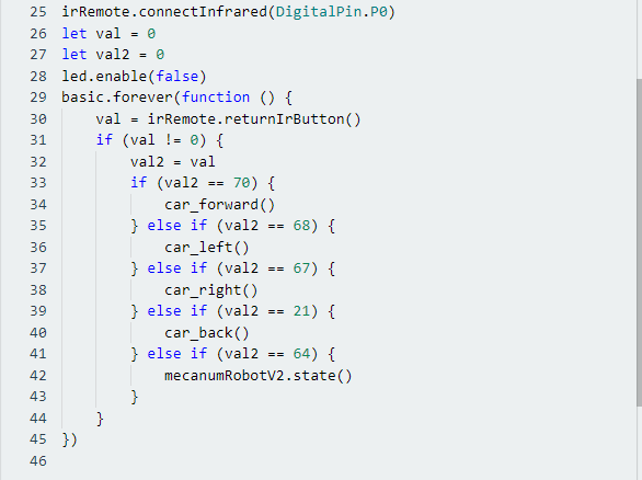
5. Test Result
Download code to micro:bit board, and dial POWER to ON end.
Make IR remote control point at micro:bit and press the button to control smart car to move.
 button makes smart car move forward,
 stands for turning left,
 implies rightward turning,
  indicates moving backward,
 stops car.
Note: The distance between IR remote control and IR receiving head of smart car are supposed less than 5m during the test.
Project 20:Bluetooth Multi-purpose Smart Car
Project 20.1:Read Bluetooth Data
1. Description
Micro:bit main board comes with a built-in Bluetooth which can be used to communicate with it. And the Micro:bit can also be controlled by Bluetooth or transmit signals back to smartphone or computer via it. This Bluetooth can communicate with the Bluetooth equipped in other devices or with Bluetooth App to control other equipment.
It is compatible with both Android system ans IOS system. And we have designed two Bluetooth Apps for both systems.
The connection of the Bluetooth on the board with these two Apps is similar. In this lesson, we will introduce the functions of all keys and patterns on the Apps and control the smart car via Bluetooth App.
2. Preparation
Insert the micro:bit board into the slot of keyestudio 4WD Mecanum Robot Car V2.0
Place batteries into battery holder
Dial power switch to ON end
Connect the micro:bit to your computer via an USB cable
Open the Web version of Makecode
If you choose to drag the code manually, you need to add the Bluetooth extension library first. Click the gear icon (Settings) in the upper right corner, then click on Extensions to go to the library file selection screen, and then click on the “Bluetooth” extension library (if it doesn’t exist, search Bluetooth to find it), as shown below:
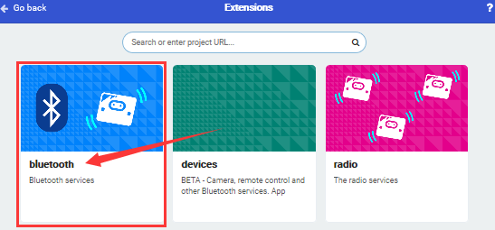
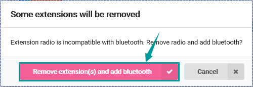
As the Bluetooth and extension radio can’t work together, therefore, their extension libraries are not compatible.
Therefore, remove extension(s) and add Bluetooth please if you see the following prompt box pop up.
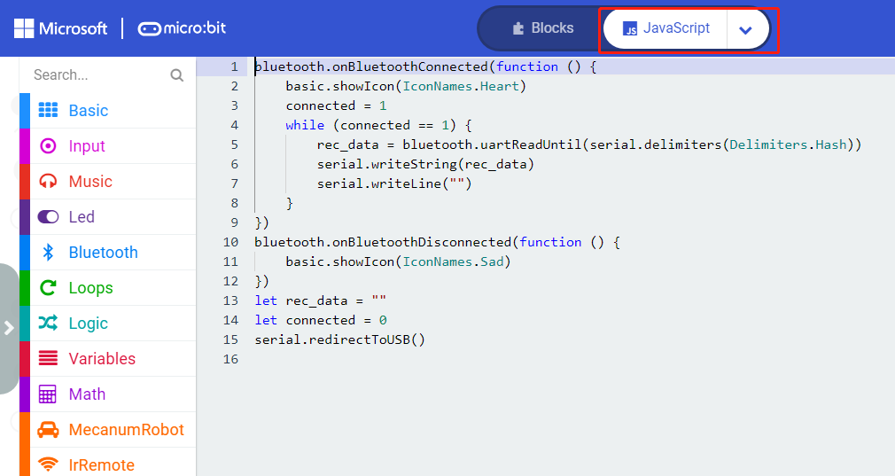
3. Test Code
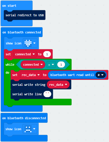
Click“JavaScript”to view the corresponding JavaScript code:
4. Test Result
If you drag blocks step by step, you need to set as follows after finishing test code.

However, you could skip this step if you directly import test code.
After setting, download code to micro:bit board, don’t plug off the USB cable.Next to download App.
For IOS System:
a. Open App Store;

b. Search mecanum_robot and click“ ”to download the Bluetooth App of mecanum_robot;
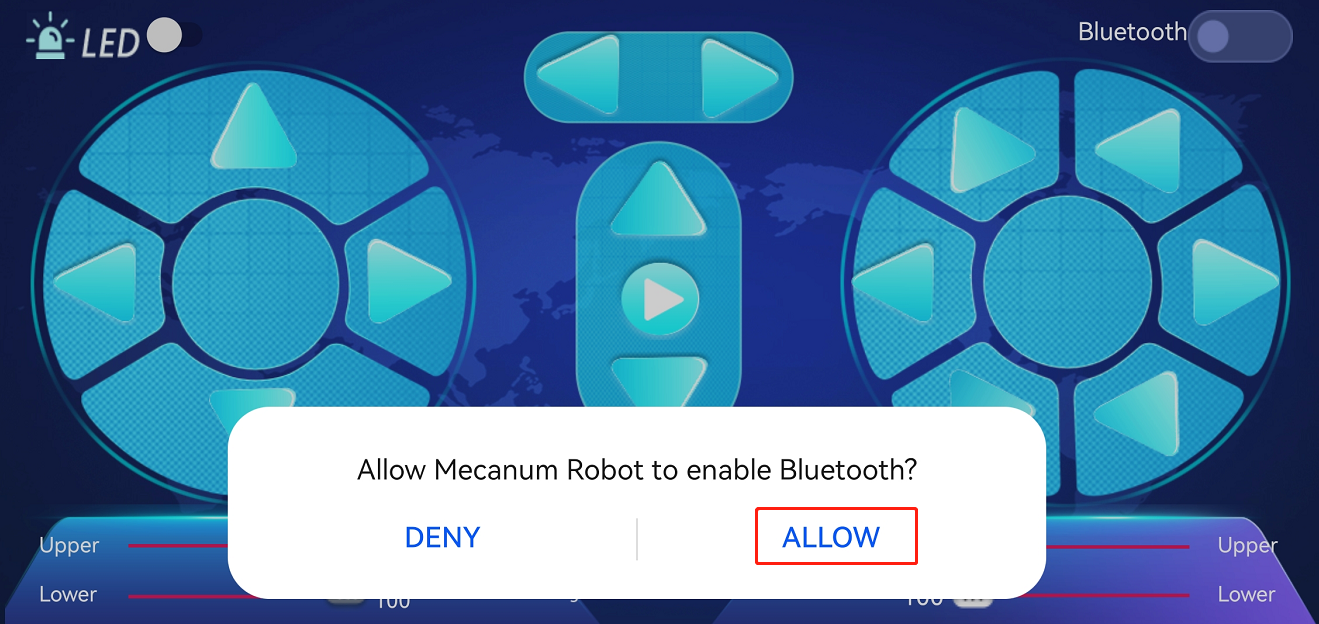
c. After downloading the APP, click “OPEN” or click the application mecanum_robot on the phone/iPad desktop to open the APP. A dialog box appears on the APP interface, and click “OK” in the dialog box.
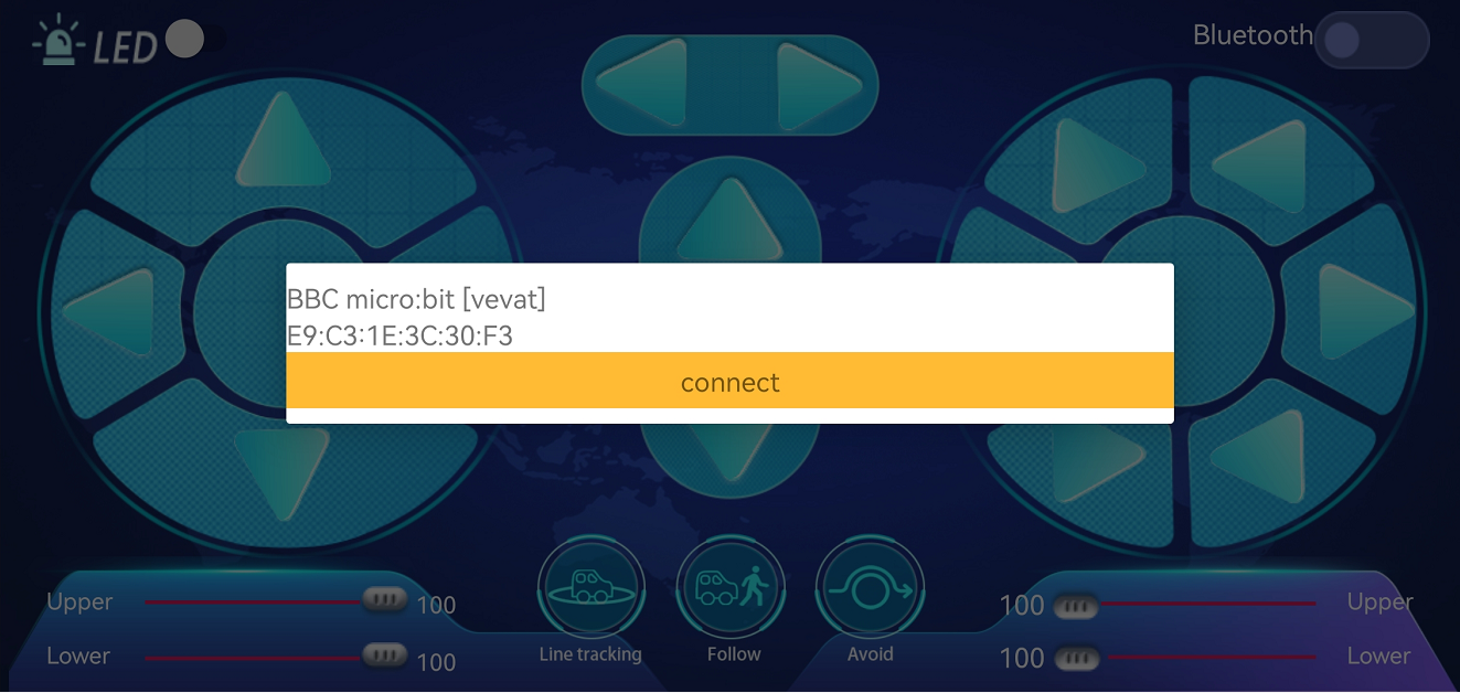
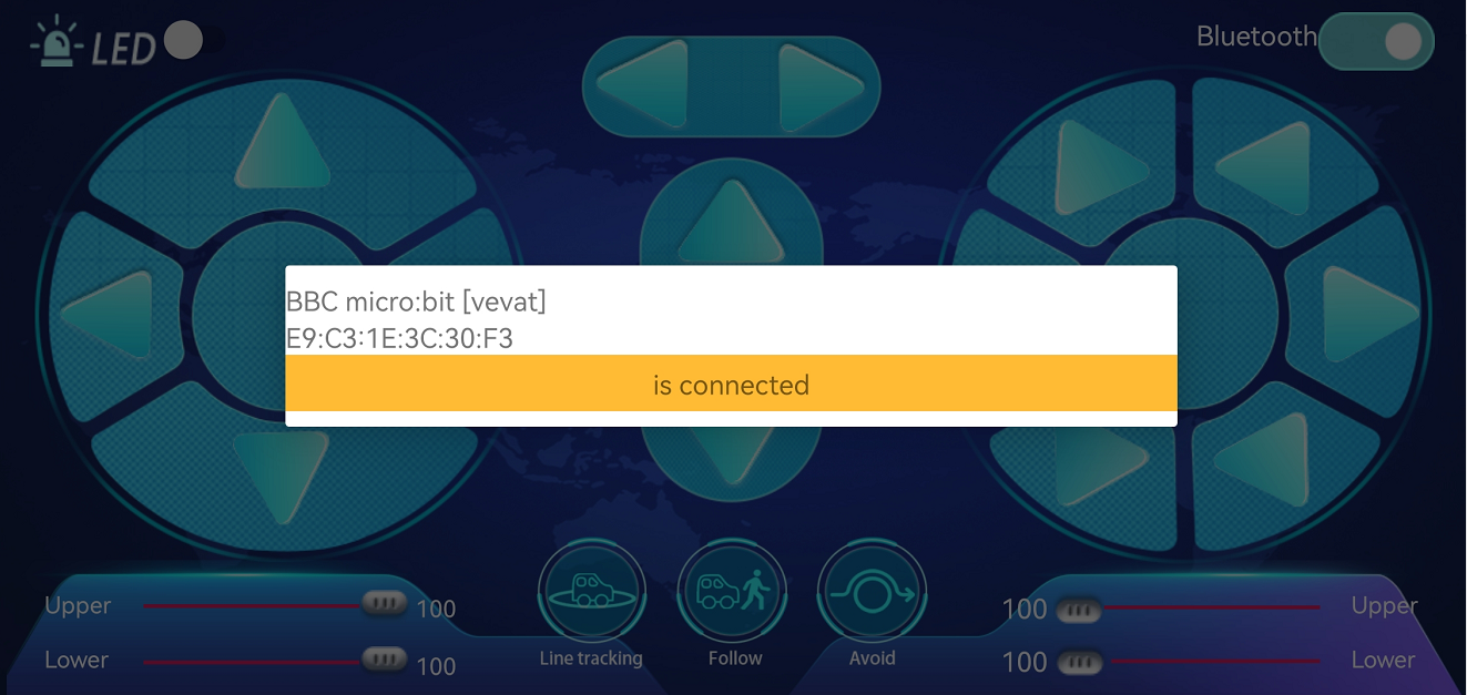
d. First turn on the Bluetooth of the mobile phone/iPad, and then click the connect button (control) in the upper left corner of the APP interface to perform a Bluetooth search. In the search results, click “BCC micro:bit”. After a few seconds, the Bluetooth is connected.
For Android System:
a. Use the scanning function in the browser to scan and identify the QR code

or enter the link:http://8.210.52.206/mecanum_robot.apk to download. After the identification is successful, click “go to website” to enter the download mecanum_robot.apk page , click “Download” to download the mecanum_robot application.
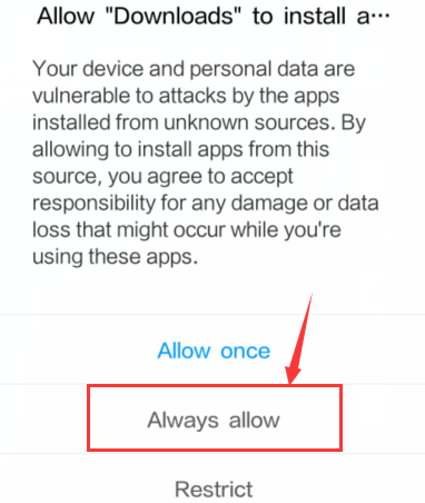
b. Click“Allow allow”to enter Installation Diagram; click“install”to install the App.
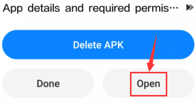
c. Click “Open” or click the application mecanum_robot on the mobile phone desktop to open the APP, and a dialog box appears. In the dialog box, click “Allow” to turn on the Bluetooth of the mobile phone. You can also turn on the phone’s Bluetooth before opening the APP.
d. Click  on the upper right corner to search for Bluetooth and click“connect”; a few seconds later, the Bluetooth is paired.
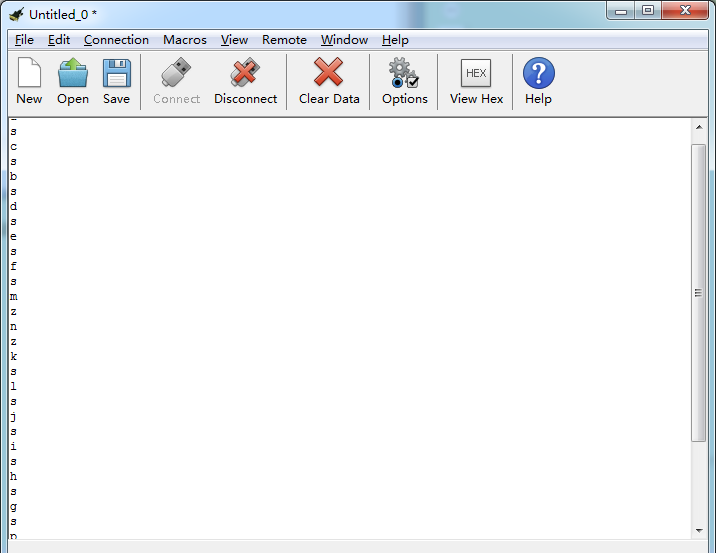
Open CoolTerm, click Options to select SerialPort. Set COM port and 115200 baud rate. Click“OK”and“Connect”.
Point at micro:bit board and press the icons on APP, the corresponding characters are shown on CoolTerm monitor.
Through the test, we get the functions of every icon, as shown below:
Project 20.2:Multi-purpose Smart Car
1. Description
In this lesson, we will control the smart car to perform multipurpose functions.
2. Preparation
Insert the micro:bit board into the slot of keyestudio 4WD Mecanum Robot Car V2.0
Place batteries into battery holder
Dial power switch to ON end
Connect the micro:bit to your computer via an USB cable
Open the Web version of Makecode
Steps: Click the gear icon (Settings) in the upper right corner, then click on Extensions to go to the library file selection screen, and then click on the “Bluetooth” extension library (if it doesn’t exist, search Bluetooth to find it), as shown below:
As the Bluetooth and extension radio can’t work together, therefore, their extension libraries are not compatible.
Therefore, remove extension(s) and add Bluetooth please if you see the following prompt box pop up.
3. Test Code
Since the code is quite long, it won’t be displayed here. You can directly go to the following path to find the corresponding code.
Click“JavaScript” to view the corresponding JavaScript code: :
4. Test Result
This experiment combines the previous projects to make the car to perform actions via Bluetooth.
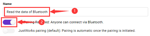
Enter Makecode online editor→Projecting Settings→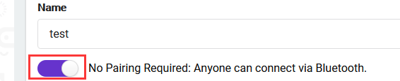 , enable “No Pairing…”(you could skip this step if you import test code directly)
Download code to micro:bit board, dial POWER to ON end, and connect the Bluetooth, then you can control the car via the Bluetooth App of mecanum_robot.
Note:  is used to adjust the speed, and
  can only be dragged.
Common Problems
1. The car has no reaction
Please check whether the batteries are sufficient
Please check whether the wirings are correct
2. Computers can’t recognize the USB ports
Please ensure whether the microbit driver is installed
Please check whether the USB wire is in good condition.