Python Tutorial
Resource Download
To help you quickly obtain related codes, libraries, and other support files for this product, please click the links below to download:
Getting started with Python
This tutorial is written for Python language. If you want to use graphical code programming, please refer to the manual “Makecode Tutorial”. In the root directory of the resource you downloaded, there is a folder named “Python tutorial”, which stores all the Python code of the Micro:bit 4WD Mecanum Robot Car V2.0. The Python code file is a file ending with “.py”.
What is MicroPython?
Python is a text-based language, which is widely used in education and is also used by professional programmers in fields such as data science and machine learning.
Micro: bit can be programmed in Python, which is a microcontroller, and the hardware differences prevent micro: bit from fully supporting Python. The MicroPython is dedicated to micro:bit,which is an efficient implementation of the Python3 programming language. It contains a small portion of the Python standard library and is optimized to run on micro: bit microcontrollers.
The version of Python used by BBC micro: bit is called MicroPython. The MicroPython is perfect for those who want to learn more about programming, which helps you program with a series of code snippets, a variety of pre-made graphics and music.
Link for BBC microbit MicroPyth:BBC micro:bit MicroPython
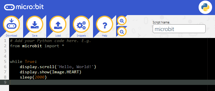
Python has two types of editors: web version and offline version
1. Web version: https://python.microbit.org/v/1.1
2. The other one is the offline compiler too—–Mu 
Official Website of Mu:https://codewith.mu/
Mu
Mu, a Python code editor, is suitable for starters. It doesn’t support 32-bit Windows.
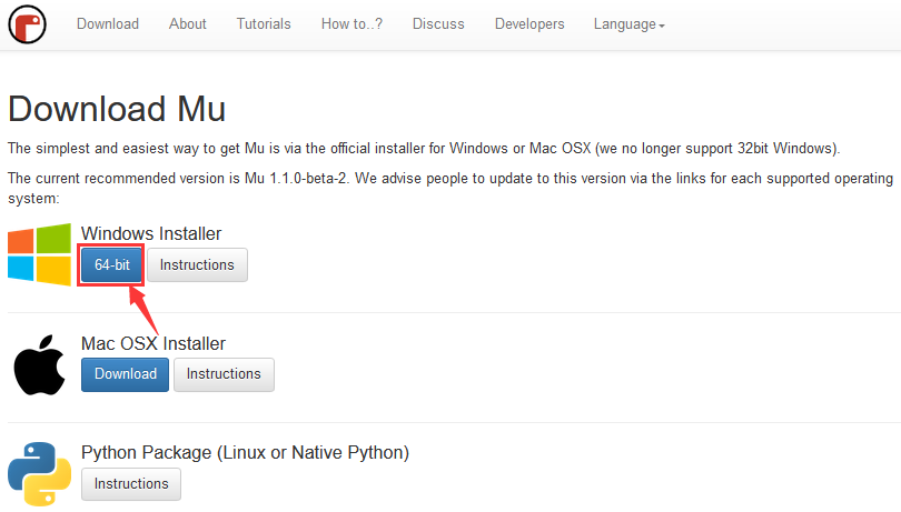
1. Download Mu
Click“This PC”and right- click to select Properties to check the version of your computer.
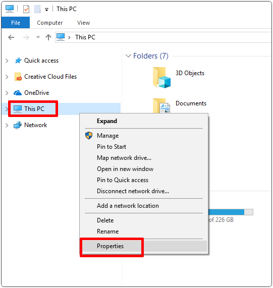
Check the system type of your computer.
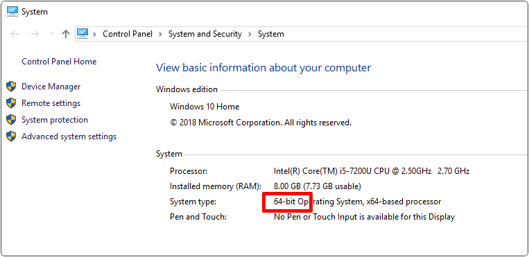
Enter the link of MU: https://codewith.mu/en/download to download the corresponding version of Mu.
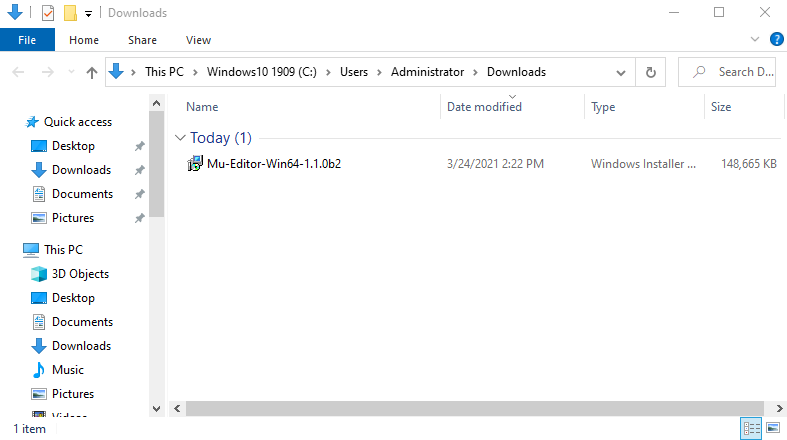
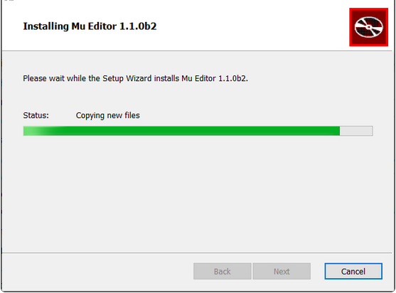
2. Run Setup
Open the file below
Mac OSX:https://codewith.mu/en/howto/1.1/install_macos.
Linux:https://codewith.mu/en/howto/1.2/install_linux.
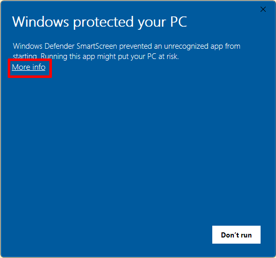
Windows 10
You will view the page pop-up, then click “More info”.
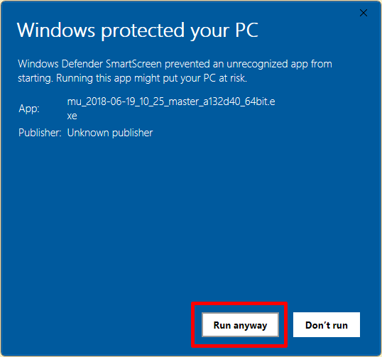
Then click“Run anyway”.
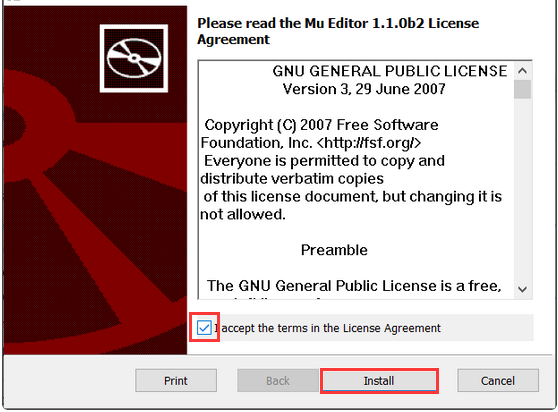
3. License Agreement
Click “Install”.
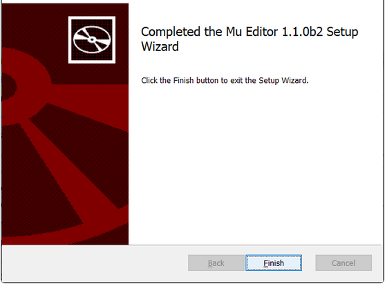
After installed , click “finish”.
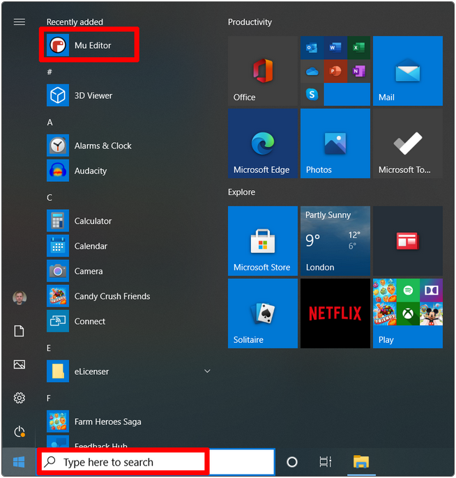
4. Start Mu
Next, find it according to the following picture
Its main interface is shown as below:
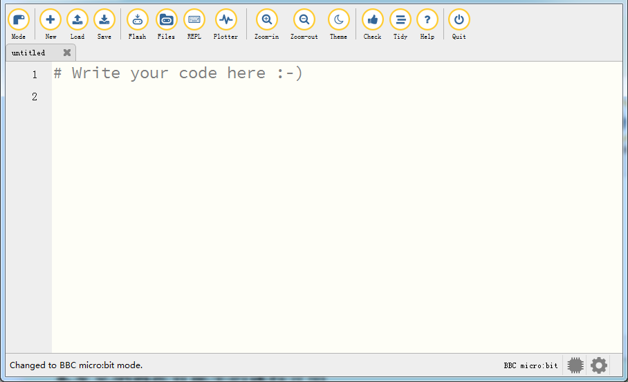
Using Modes & Menu Bar
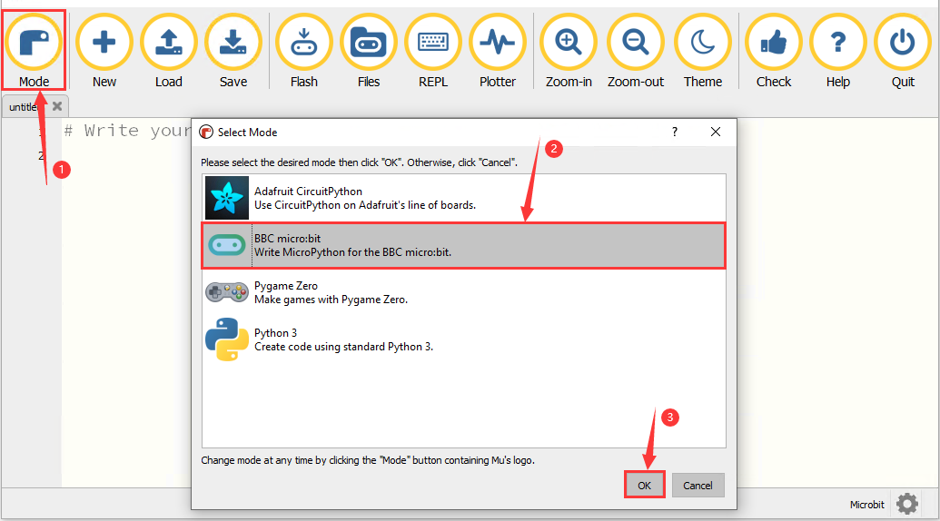
Set “Mode” to BBC micro:bit .
On the menu, click “Mode” to set it to “BBC micro:bit”. The micro:bit mode understands how to interact with and connect to a micro:bit.
Click to Start with Mu.
How Mu Import Library to Micro:bit
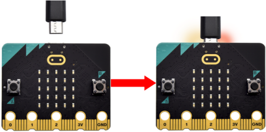
Before importing libraries, we need to upload a .py code (empty code is also ok) to the micro:bit board. Here we take an empty code as an example.
Connect the board to computer via USB cable. Open the Mu and click “Flash” to upload the .py code (empty code) to the board.
In this tutorial, “keyes_mecanum_Car_V2.py” library file are used. Therefore, import the “keyes_mecanum_Car_V2.py” library file into the micro:bit. This file contains the control method of the Micro:bit 4WD Mecanum Robot Car V2.0.
The default directory for Mu to save files is “mu_code”in the root directory of the user’s directory.
References link: https://codewith.mu/en/tutorials/1.0/files
the Methods of finding the “mu_code” folder:
Method One:
For example, on the windows system, suppose your system is installed on the C driver of the computer, and the user name is “Administrator”, then the path of the “mu_code” directory is “C:\Users\Administrator\mu_ code”. On Linux systems, the path of the “mu_code” directory is “~/home/mu_code”.
Open the “mu_code”folder.

Method Two:
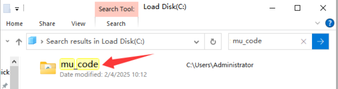
Search for the “mu_code” folder on the Disk(C:).
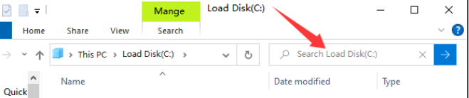
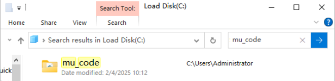
Open “mu_code”.
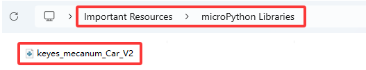
The path of the data folder where the “keyes_mecanum_Car.py”library file we provide are located is as follows:
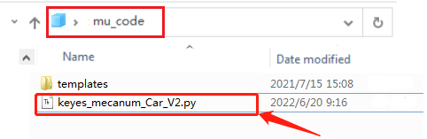
Copy“keyes_mecanum_Car.py”library file to the folder“mu_code”。When the copy is done, as shown below:
First open the Mu software and connect the micro:bit to your computer then click the “Files” button, and drag the “keyes_mecanum_Car.py” library file to the micro:bit.
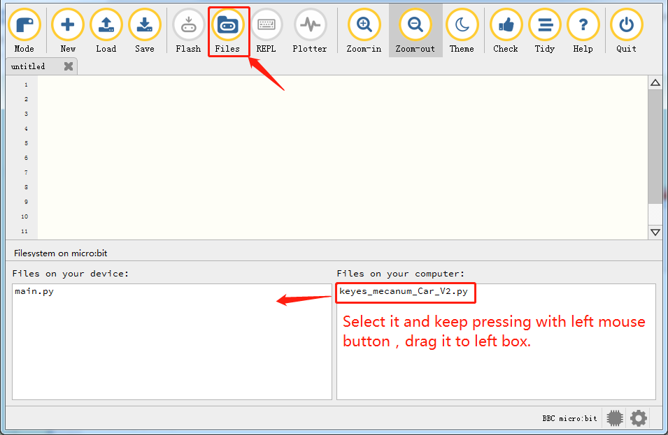
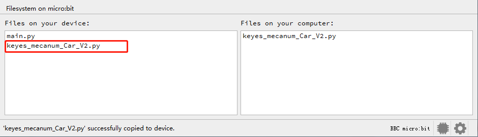
After a few seconds, the import is complete and you can see it in the box on the left.
Projects
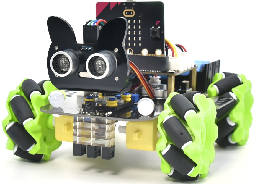
Note: project 1 to 12 will be conducted with the built-in sensors an LED dot matrix of the Micro:bit mainboard V2
Project 1:Heart Beat
1. Description
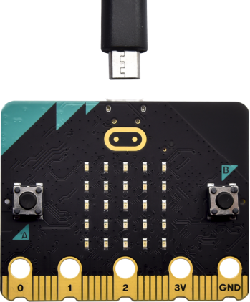
This project is easy to conduct solely with a micro:bit main board and icro USB cable. This experiment serves as a starter for your to entr o the magical programming world of the micro:bit.
2. Preparation
A. Attach the micro:bit main board to your computer via the USB cable
B. Open the offline version of Mu.
3. Test Code
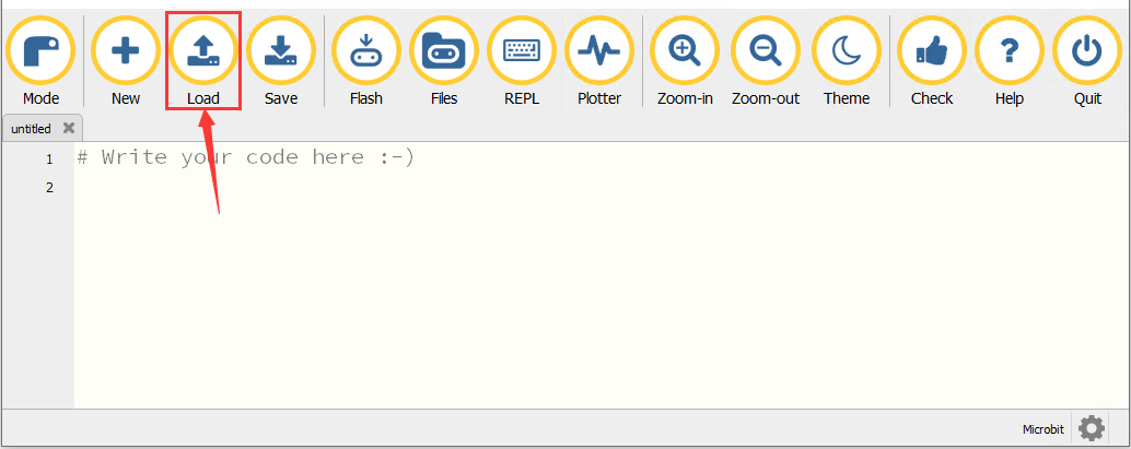
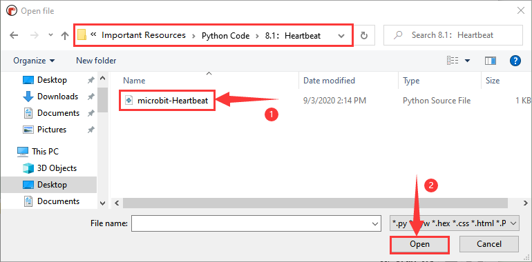
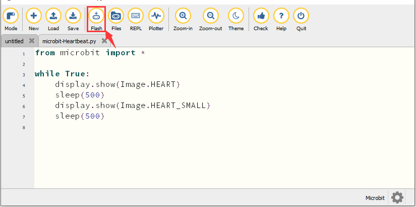
Open the Mu software, tap“Load”, select““microbit-Heartbeat.py“ file and click“open”:
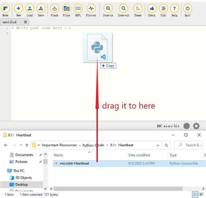
There is another way to import code. Open the Mu software and drag file”microbit-Heartbeat.py”into it.
You can also input code in the edit window yourself.
(Note: All English words and symbols must be written in English.)
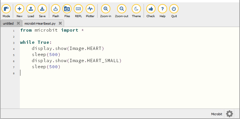
from microbit import *

while True:
    display.show(Image.HEART)
    sleep(500)
    display.show(Image.HEART_SMALL)
    sleep(500)
The following are a list of built-in images:
• Image.HEART
• Image.HEART_SMALL
• Image.HAPPY
• Image.SMILE
• Image.SAD
• Image.CONFUSED
• Image.ANGRY
• Image.ASLEEP
• Image.SURPRISED
• Image.SILLY
• Image.FABULOUS
• Image.MEH
• Image.YES
• Image.NO
• Image.CLOCK12, Image.CLOCK11, Image.CLOCK10, Image.CLOCK9 mage.CLOCK8, Image.CLOCK7, Image.CLOCK6, Image.CLOCK5,
Image.CLOCK4, Image.CLOCK3, Image.CLOCK2,Image.CLOCK1
• Image.ARROW_N, Image.ARROW_NE, Image.ARROW_E, Image.ARROW_SE mage.ARROW_S, Image.ARROW_SW, Image.ARROW_W, Image.ARROW_NW
• Image.TRIANGLE
• Image.TRIANGLE_LEFT
• Image.CHESSBOARD
• Image.DIAMOND
• Image.DIAMOND_SMALL
• Image.SQUARE
• Image.SQUARE_SMALL
• Image.RABBIT
• Image.COW
• Image.MUSIC_CROTCHET
• Image.MUSIC_QUAVER
• Image.MUSIC_QUAVERS
• Image.PITCHFORK
• Image.PACMAN
• Image.TARGET
• Image.TSHIRT
• Image.ROLLERSKATE
• Image.DUCK
• Image.HOUSE
• Image.TORTOISE
• Image.BUTTERFLY
• Image.STICKFIGURE
• Image.GHOST
• Image.SWORD
• Image.GIRAFFE
• Image.SKULL
• Image.UMBRELLA
• Image.SNAKE,Image.ALL_CLOCKS,Image.ALL_ARROWS
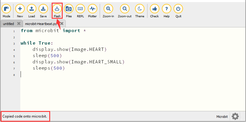
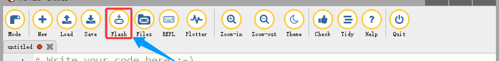
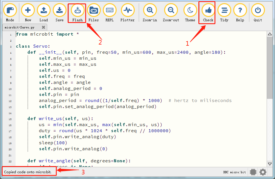
Connect the micro:bit board to computer via an USB cable, click“Flash”to download code to the board.
The code, even it is wrong, can be downloaded to the micro:bit board successfully, but can not work on micro:bit board.
Click“Flash”to download code to micro:bit.
Click“REPL”and press the reset button on micro:bit, the error information will be displayed on the REPL window, as shown below:
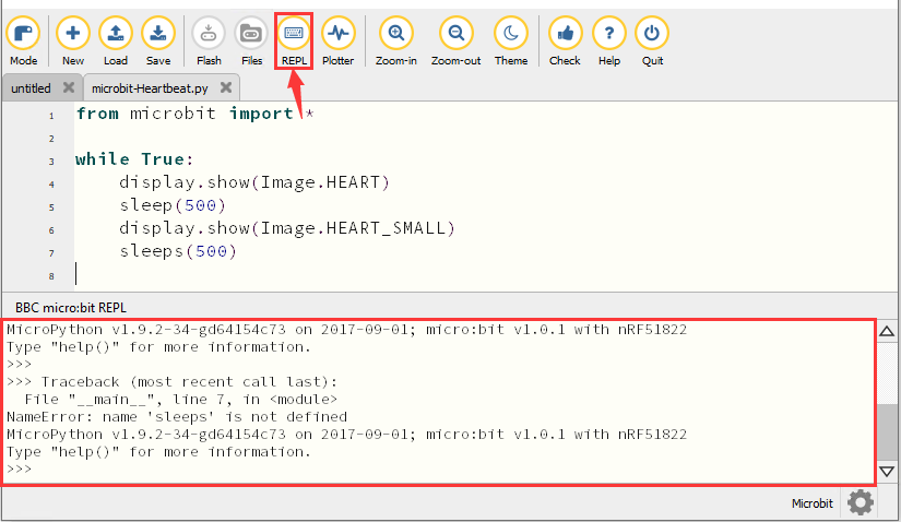
Click“REPL”again to turn off the REPL mode, then you could refresh new code.
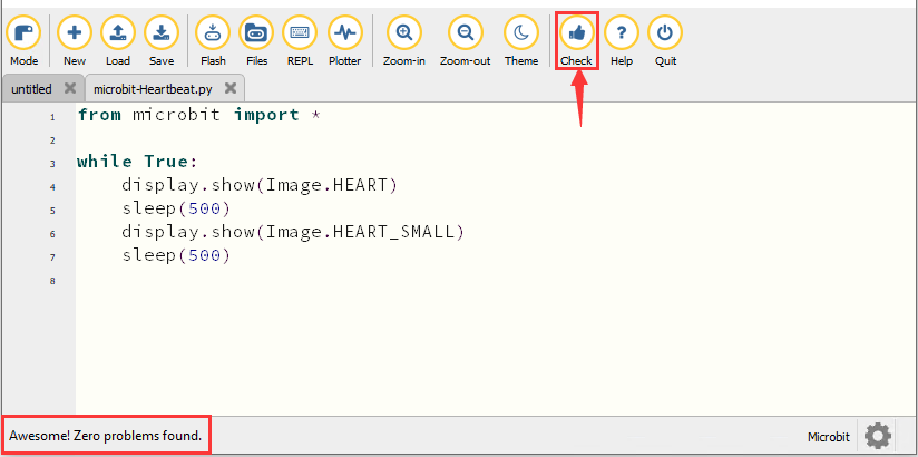
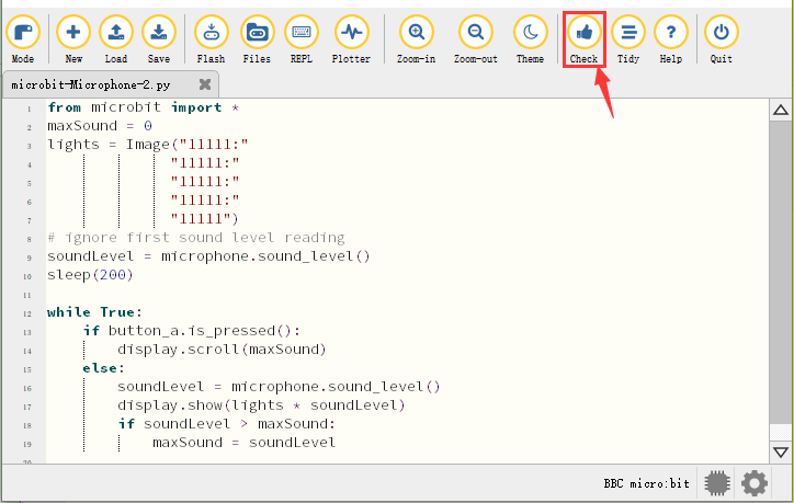
To make sure the correct code, you only need to tap“Check”. The errors will be shown on the window.
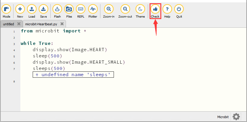
Modify the code according to the prompt and click“Check”.
Please log in the website for more tutorials:https://codewith.mu/en/tutorials/
4. Test Result
Click “Flash” to load the code to the micro:bit board.
After downloading the code to the board successfully, power on via micro USB cable or external power supply(turn the DIP switch to ON), and press the reset button on the board.
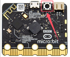
The LED dot matrix shows the pattern “❤”and then “ ”alternatively.
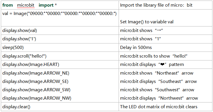
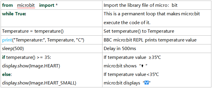
5. Code Explanation
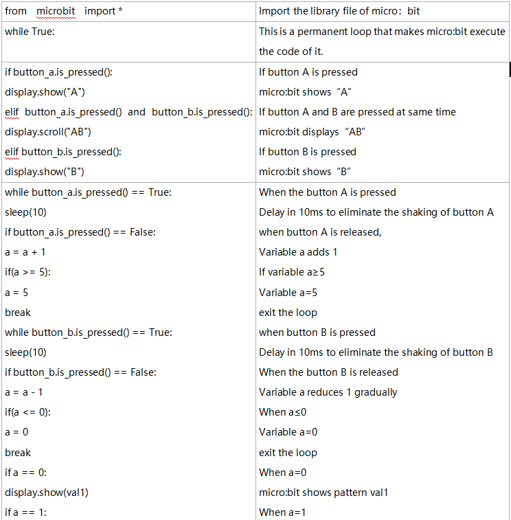
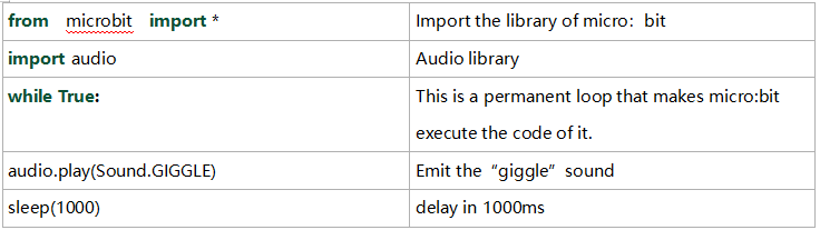
from microbit import* |
Import the library file of micro:bit |
|---|---|
while True: |
This is a permanent loop that makes micro:bit execute the code i his loop forever. |
display.show(Image.HEART) |
micro:bit shows “❤” |
sleep(500) |
Delay in 500ms |
display.show(Image.HEART_SMALL) |
The LED dot matrix displays“ |
Project 2:Light A Single LED
1. Description
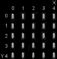
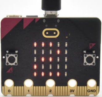
The LED dot matrix consists of 25 Diodes arranged in a 5 by 5 square and placed at the intersection of row lines (X) and column lines (Y). We can control one of the 25 LEDs by setting coordinate points. For example, the first LED sits in the first line is (0,0)and the third LED positioned in the first line is (2,0)and others likewise.
2. Preparation
A. Attach the micro:bit main board to your computer via the USB cable
B. Open the offline version of Mu.
3. Test Code
Enter the Mu software and open the“Single LED display.py.”file to import code.You can also input code in the editing window yourself.
(Note: All English words and symbols must be written in English)
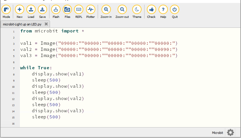
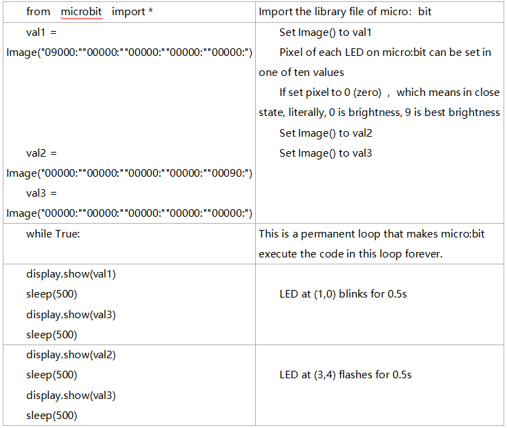
from microbit import *

val1 = Image("09000:""00000:""00000:""00000:""00000:")
val2 = Image("00000:""00000:""00000:""00000:""00090:")
val3 = Image("00000:""00000:""00000:""00000:""00000:")

while True:
    display.show(val1)
    sleep(500)
    display.show(val3)
    sleep(500)
    display.show(val2)
    sleep(500)
    display.show(val3)
    sleep(500)
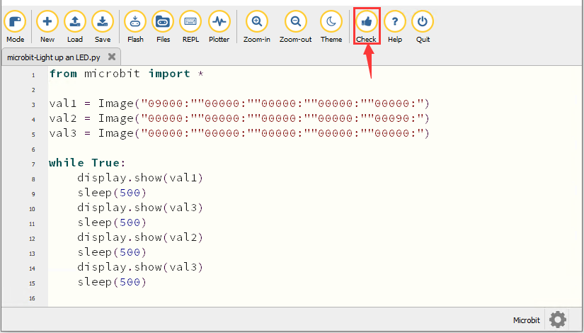
Click“Check”to examine error in the code. The program proves wrong if underlines and cursors are shown.
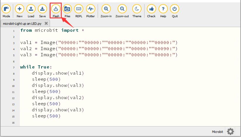
If the code is correct, connect the micro:bit to your computer and click“Flash”to download code to micro:bit board.
4. Test Result
After downloading the code to the board successfully, power on via micro USB cable or external power supply(turn the DIP switch to ON), and press the reset button on the board.
The LED in (1,0) will be on and off for 0.5s and the one in (3,4) will be on and off for 0.5s and repeat this sequence.
5. Code Explanation
6. Reference
sleep(ms) : delay time
For more details about delay, please refer to the link: https://microbit-micropython.readthedocs.io/en/latest/utime.html
Project 3:5*5 LED Dot Matrix
1. Description
Dot matrix is very commonplace in daily life, which has found wide applications in LED advertisement screens, elevator floor display, bus stop announcement and so on. The LED dot matrix of Micro: Bit main board contains 25 Diodes. Previously, we have succeeded in controlling a certain LED via its position point. Supported by the same theory, we can turn on many LEDs at the same time to showcase patterns, digits and characters.
What’s more, we can also click”show icon“ to choose the pattern we like to display. Last but not the least, we can design patterns by ourselves as well.
2. Preparation
A. Attach the micro:bit main board to your computer via the USB cable
B. Open the offline version of Mu.
3. Test Code1
You could open“5×5 LED Dot Matrix-1.py”file to import the code. You can also input code in the editing window yourself.
(Note: All words and symbols must be written in English.)
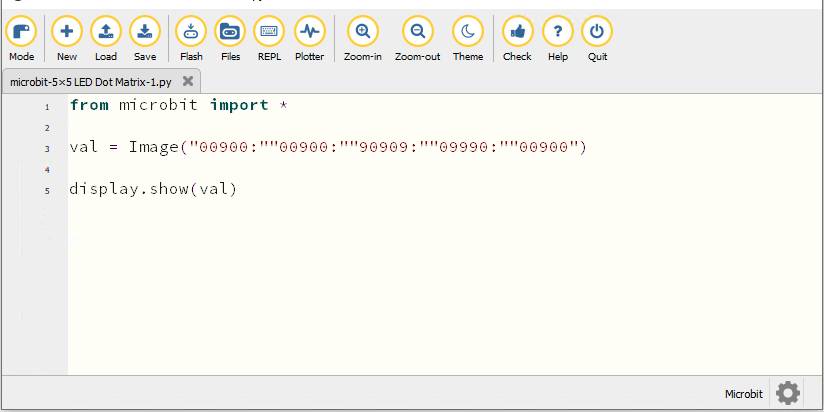
from microbit import *

val = Image("00900:""00900:""90909:""09990:""00900")

display.show(val)
Click“Check”to examine the error in the code. The program proves wrong if underlines and cursors are shown.
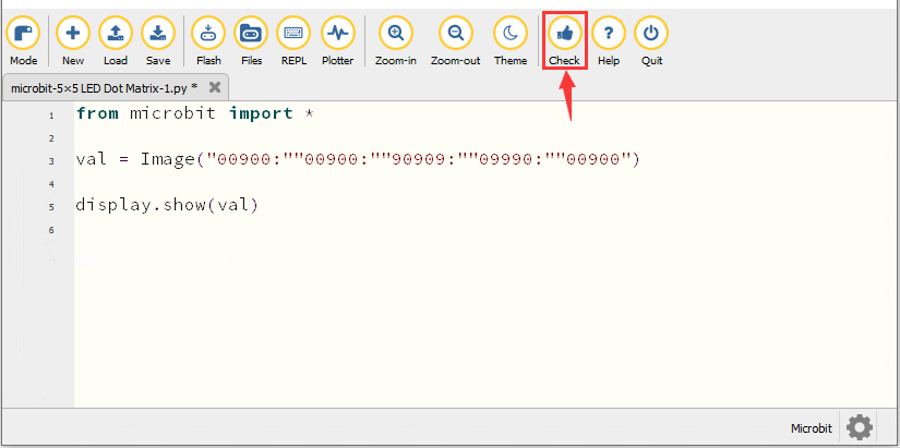
If the code is correct, connect micro:bit to computer and click“Flash”to download code to micro:bit board.
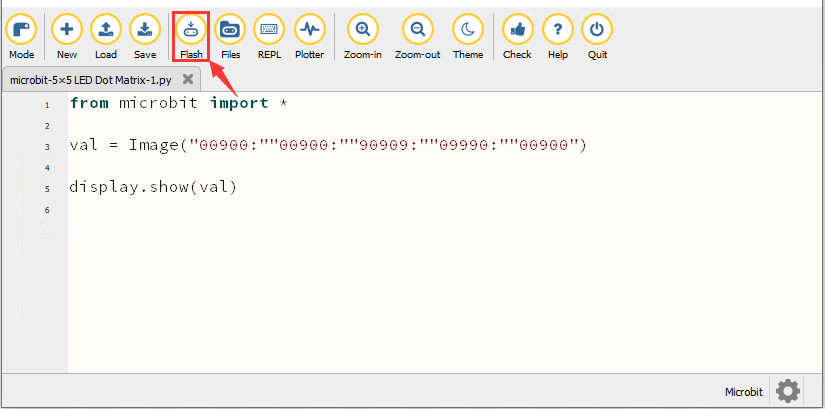
4. Test Result1
After downloading the code to the board successfully, power on via micro USB cable or external power supply(turn the DIP switch to ON), and press the reset button on the board.
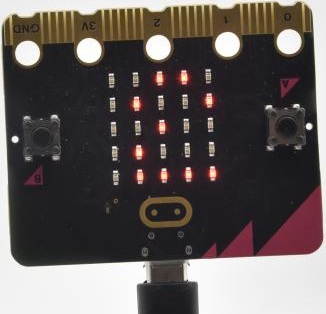
We will find that the 5*5 dot matrix start to show a downward arrow 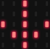 .
.
5. Test Code2
You could open “5×5 LED Dot Matrix-2.py“ file to import the code. You can also input code in the editing window yourself.
(Note: All words and symbols must be written in English.)
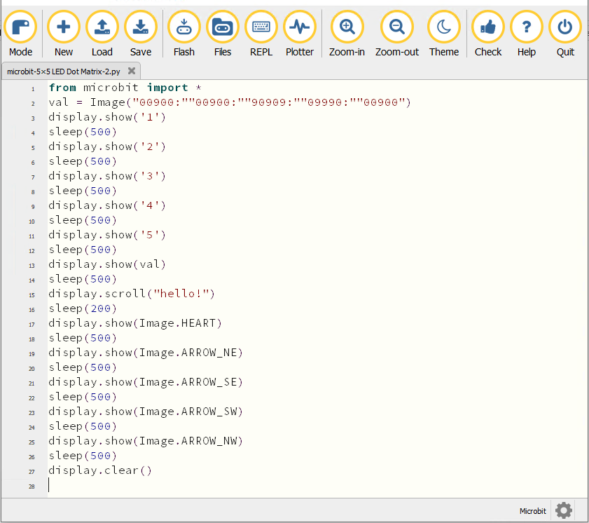
from microbit import *
val = Image("00900:""00900:""90909:""09990:""00900")
display.show('1')
sleep(500)
display.show('2')
sleep(500)
display.show('3')
sleep(500)
display.show('4')
sleep(500)
display.show('5')
sleep(500)
display.show(val)
sleep(500)
display.scroll("hello!")
sleep(200)
display.show(Image.HEART)
sleep(500)
display.show(Image.ARROW_NE)
sleep(500)
display.show(Image.ARROW_SE)
sleep(500)
display.show(Image.ARROW_SW)
sleep(500)
display.show(Image.ARROW_NW)
sleep(500)
display.clear()
Click“Check”to examine errors in the code. The program proves wrong if underlines and cursors are shown.
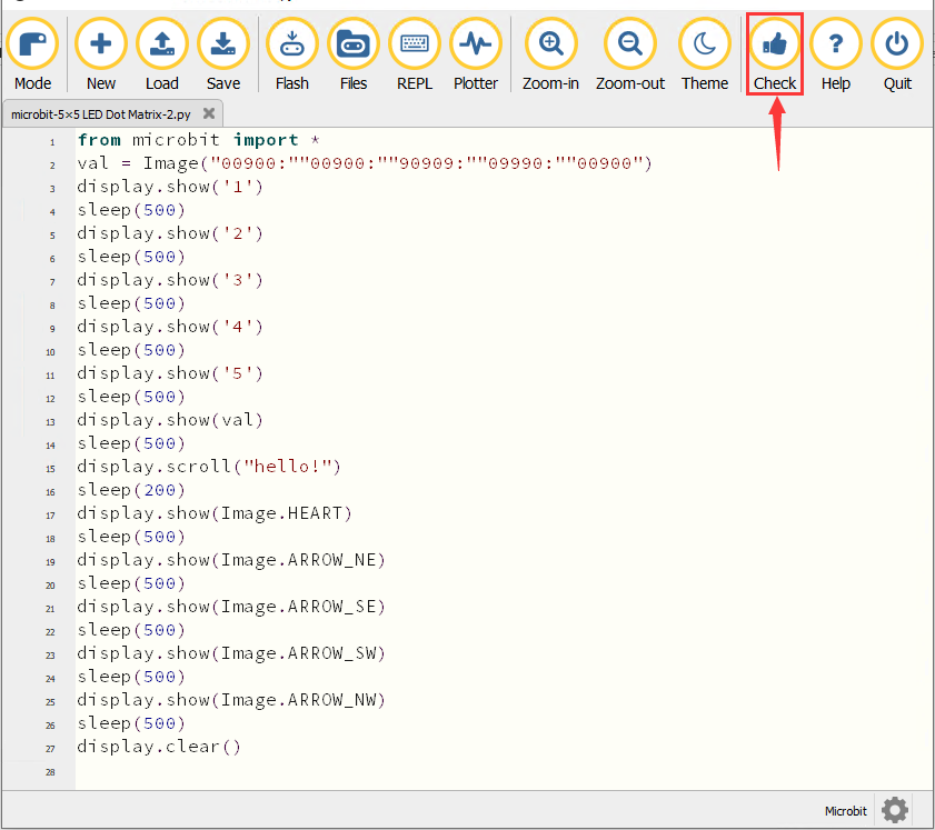
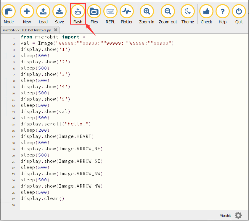
If the code is correct, connect the micro:bit to the computer and click“Flash”to download code to micro:bit board.
6. Test Result2
After downloading the code to the board successfully, power on via micro USB cable or external power supply(turn the DIP switch to ON), and press the reset button on the board.
We will find that the 5*5 dot matrix start to show numbers 1,2,3,4 and 5 and then it alternatively shows a downward arrow word,“Hello”, a heart pattern  , arrow pointing at northeast
  , then at southeast
 then at southwest
  and then at northwest
  .
.
7. Code Explanation
Reference
display.scroll() :
The display scrolls to show the values, if it is integer or float, we will use str()to transfer it into character strings.
More details, please refer to th ink:https://microbit-micropython.readthedocs.io/en/latest/utime.html
Project 4:Programmable Buttons
1. Description
Buttons can be used to control circuits. In an integrated circuit with a push button, the circuit is connected when pressing the button and but after release, it will break again.
Both ends of the button like two mountains. There is a river in between. The internal metal piece connect the two sides to let the current pass, just like building a bridge to connect two mountains.
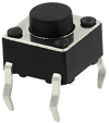
The internal structure of the button is shown as follows: before pressing the button, 1 ,2 , 3 and 4 are turned on. However, 1, 3 or 1, 4 or 2, 3 or 2 and 4 are disconnected, which is only enabled when the button is pressed. 
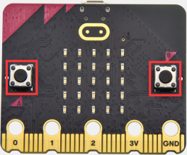
Micro: Bit main board boasts three push buttons, two are programmable buttons(marked with A and B), and the one on the other side is a reset button. By pressing the two programmable buttons can input three different signals. We can press button A or B alone or press them together and the LED dot matrix shows A,B and AB respectively. Let’s get started.
2. Preparation
A. Attach the micro:bit main board to your computer via the USB cable
B. Open the offline version of Mu.
3. Test Code1
Enter Mu software and open the file“Programmable Buttons-1.py”to import the code. You can also input code in the editing window yourself.
(Note: All words and symbols must be written in English.)
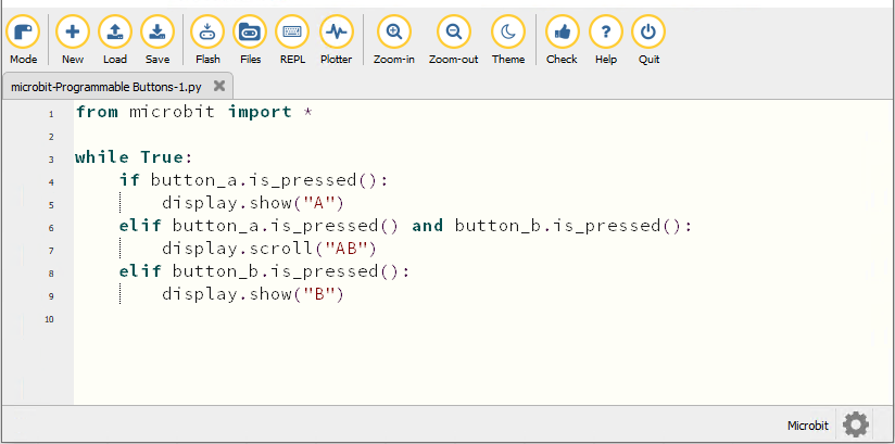
from microbit import *

while True:
    if button_a.is_pressed():
        display.show("A")
    elif button_a.is_pressed() and button_b.is_pressed():
        display.scroll("AB")
    elif button_b.is_pressed():
        display.show("B")
Click“Check”to examine errors in the code. The program proves wrong if underlines and cursors are shown.
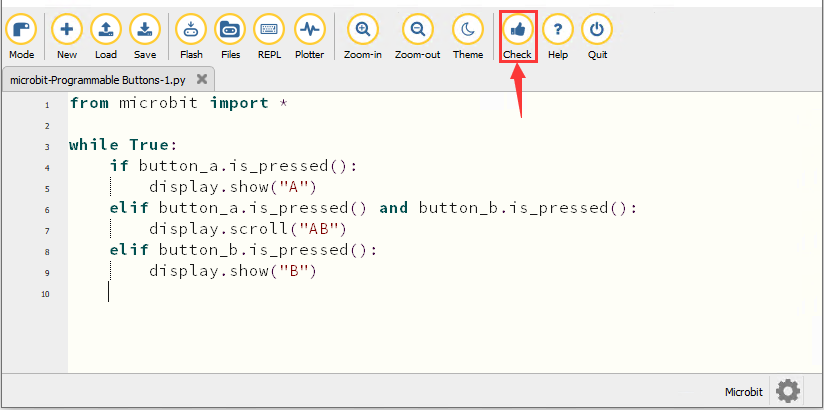
If the code is correct, connect the micro:bit to your computer and click“Flash”to download the code to the micro:bit board.
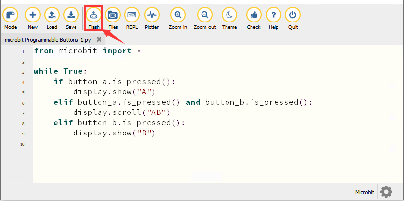
4. Test Result1
After downloading the code to the board successfully, power on via micro USB cable or external power supply(turn the DIP switch to ON), and press the reset button on the board.
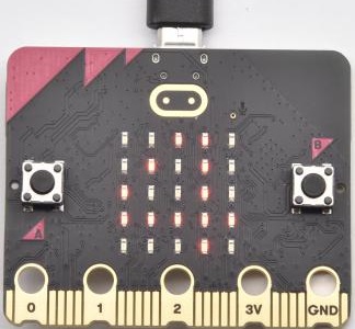
The 5*5 LED dot matrix shows “A”if button A is pressed, then“B” if button B is pressed, and “AB” if button A and B are pressed together.
5. Test Code2
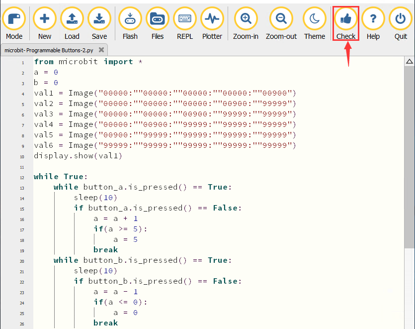
Enter Mu software and open the file“Programmable Buttons-2.py”to import the code. You can also input code in the editing window yourself.
(Note: All words and symbols must be written in English.)
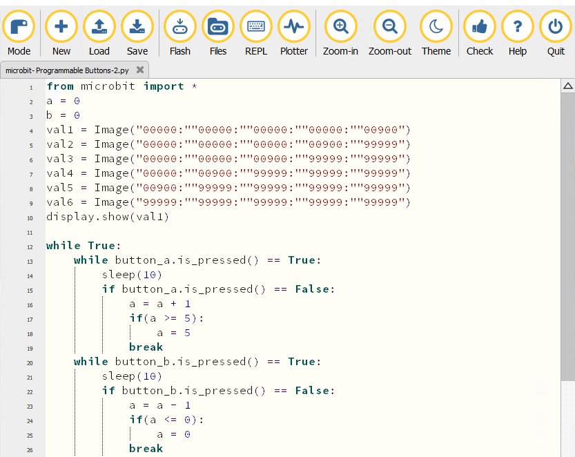
from microbit import *
a = 0
b = 0
val1 = Image("00000:""00000:""00000:""00000:""00900")
val2 = Image("00000:""00000:""00000:""00900:""99999")
val3 = Image("00000:""00000:""00900:""99999:""99999")
val4 = Image("00000:""00900:""99999:""99999:""99999")
val5 = Image("00900:""99999:""99999:""99999:""99999")
val6 = Image("99999:""99999:""99999:""99999:""99999")
display.show(val1)
while True:
while button_a.is_pressed() == True:
sleep(10)
if button_a.is_pressed() == False:
a = a + 1
if(a >= 5):
a = 5
break
while button_b.is_pressed() == True:
sleep(10)
if button_b.is_pressed() == False:
a = a - 1
if(a <= 0):
a = 0
break
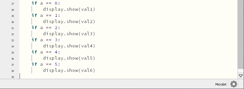
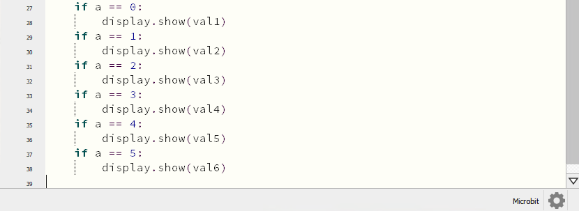
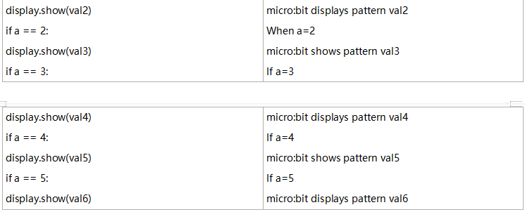
if a == 0:
display.show(val1)
if a == 1:
display.show(val2)
if a == 2:
display.show(val3)
if a == 3:
display.show(val4)
if a == 4:
display.show(val5)
if a == 5:
display.show(val6)
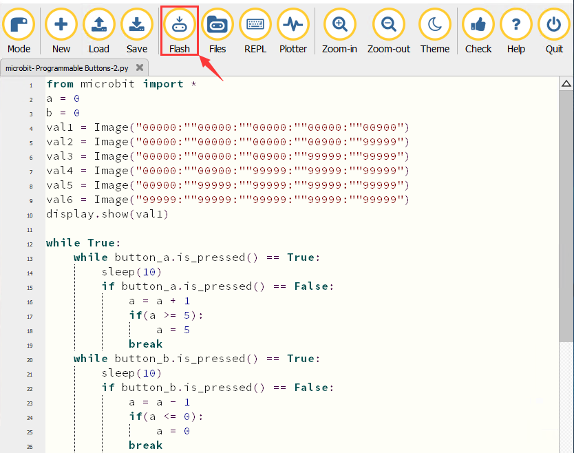
Click“Check”to examine errors in the code. The program proves wrong if underlines and cursors are shown.
If the code is correct, connect the micro:bit to your computer and click“Flash”to download the code to the micro:bit board.
6. Test Result2
After downloading the code to the board successfully, power on via micro USB cable or external power supply(turn the DIP switch to ON), and press the reset button on the board.
If the button A is pressed, the LEDs turning red increase while if the button B pressed, the LEDs turning red reduce.
7. Code Explanation
Project 5:Temperature Detection
1. Description
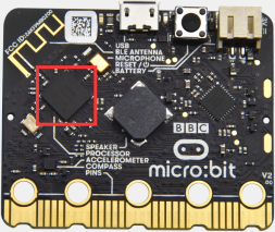
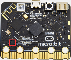
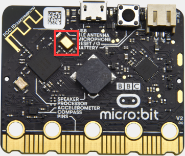
The Micro:bit main board is not equipped with a temperature sensor, but uses the built-in temperature sensor in NFR52833 chip for temperature detection. Therefore, the detected temperature is more closer to the temperature of the chip, and there maybe deviation from the ambient temperature.
In this project, we will seek to use the sensor to test the temperature in the current environment, and display the test results in the display data (device). And then control the LED dot matrix to display different patterns by setting the temperature range detected by the sensor.
Note: the temperature sensor of Micro:bit main board is shown below:
2. Preparation
A. Attach the micro:bit main board to your computer via the USB cable
B. Open the offline version of Mu.
3. Test Code1
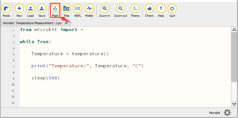
Enter Mu software and open the file“Temperature Measurement -1.py “ to import code. You can also input code in the editing window yourself.
(Note: All words and symbols must be written in English.)
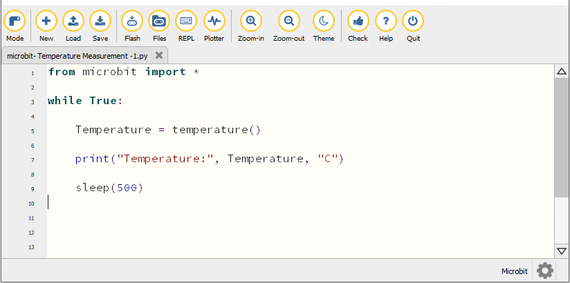
from microbit import *

while True:

    Temperature = temperature()

    print("Temperature:", Temperature, "C")

    sleep(500)
Click“Check”to examine error in the code. The program proves wrong if underlines and cursors are shown.
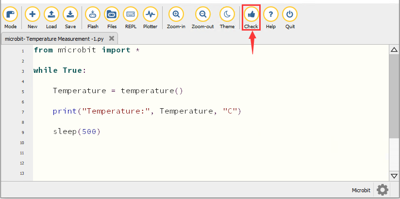
If the code is correct, connect micro:bit to computer and click“Flash”to download code to micro:bit board.
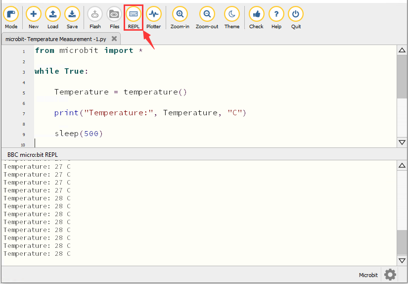
4. Test Result1
After downloading the code to the board successfully, power on via micro USB cable or external power supply(turn the DIP switch to ON). Click“REPL”and press the reset button on micro:bit.
Then REPL window will show the ambient temperature value, as shown below: (C stands for temperature unit)
5. Test Code2
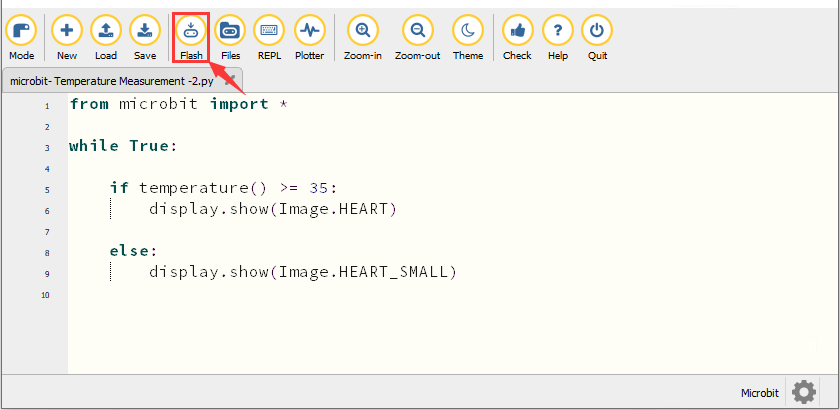
Enter Mu software and open the file“Temperature Measurement -2.py “ to import code. You can also input code in the editing window yourself.
(Note: All words and symbols must be written in English.)
The temperature value can be set in compliance with the rea emperature.
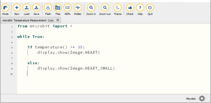
from microbit import *

while True:

    if temperature() >= 35:
        display.show(Image.HEART)

    else:
        display.show(Image.HEART_SMALL)
Click“Check”to examine error in the code. The program proves wrong if underlines and cursors are shown.
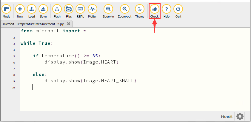
If the code is correct, connect the micro:bit to the computer and click“Flash”to download the code to the micro:bit board.
6. Test Result2
After downloading the code to the board successfully, power on via micro USB cable or external power supply(turn the DIP switch to ON), and press the reset button on micro:bit.
When the ambient temperature is less than 35℃, the 5*5 LED dot matrix shows 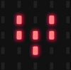 . When the temperature is equivalent to or greater than 35℃, the pattern
  appears.
7. Code Explanation
Project 6:Geomagnetic Sensor
1. Description
This project mainly introduces the use of the micro:bit’s geomagnetic sensor. In addition to detecting the strength of the magnetic field, it can also be used to determine the direction, which is an important part of the heading and attitude reference system (AHRS) as well.
It uses FreescaleMAG3110 three-axis magnetometer. Its I2C interface communicates with the outside, and the range is ±1000µT, the maximum data update rate is 80Hz. Combined with an accelerometer, it can calculate the position. Additionally, it is applied to magnetic detection and compass blocks.
Then we could read the value detected by it to determine the location. We need to calibrate the micro:bit board when the magnetic sensor works. The correct calibration method is to rotate the micro:bit board.
In addition, the objects nearby may affect the accuracy of readings and calibration.
2. Preparation
A. Attach the micro:bit main board to your computer via the USB cable
B. Open the offline version of Mu.
3. Test Code1
Enter Mu software and open the file“Magnetic sensor -1.py“ to import code. You can also input the code in the editing window yourself.
(Note: All words and symbols must be written in English.)
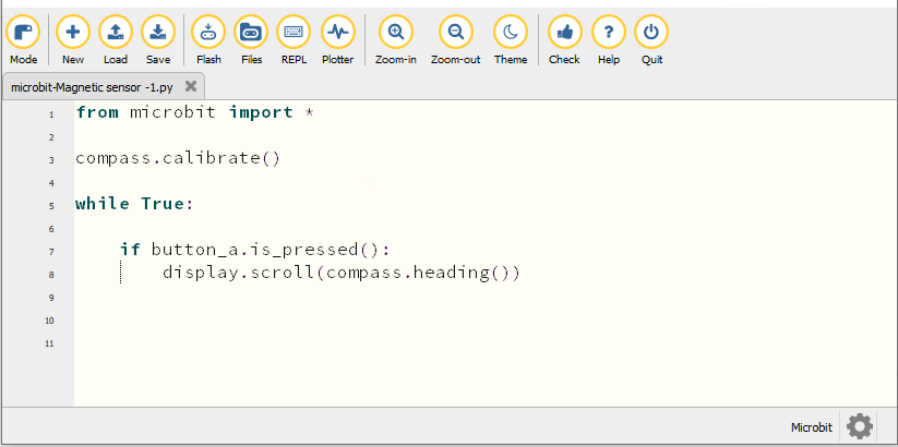
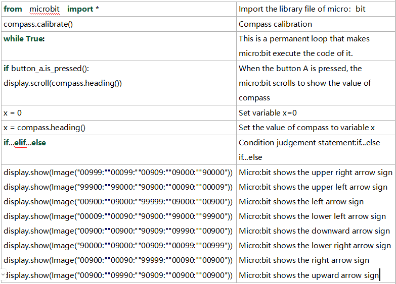
from microbit import *

compass.calibrate()

while True:

    if button_a.is_pressed():
        display.scroll(compass.heading())
Click“Check”to examine errors in the code. The program proves wrong if underlines and cursors are shown.
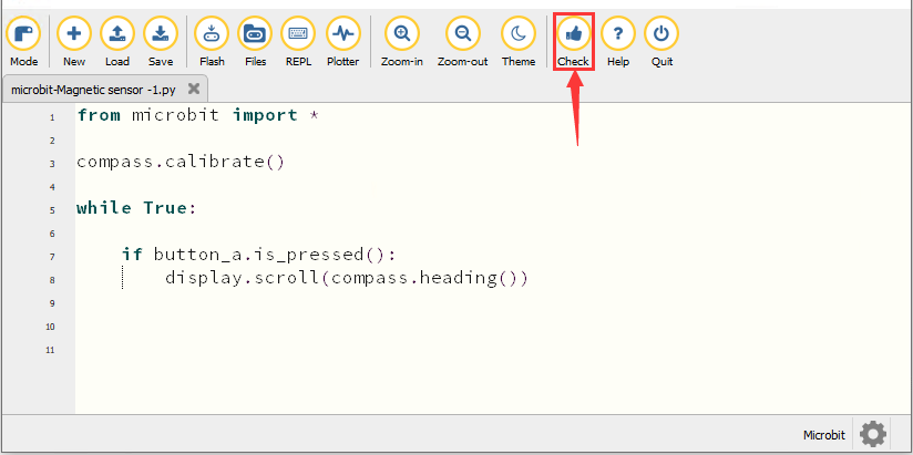
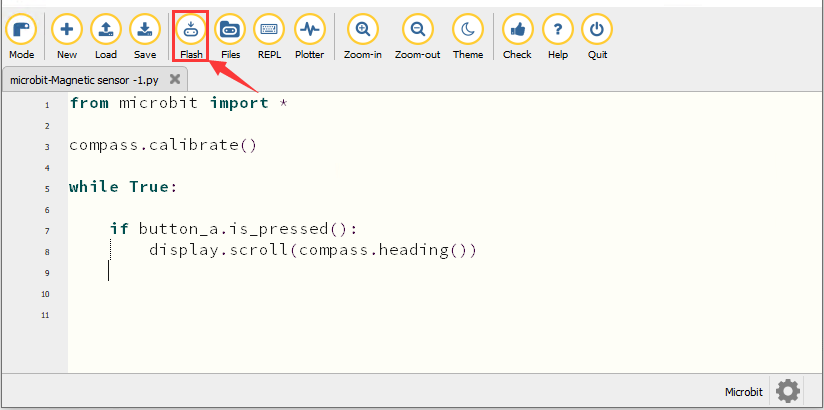
If the code is correct, connect micro:bit to the computer and click“Flash”to download the code to the micro:bit board.
4. Test Result1
After downloading the code to the board successfully, power on via micro USB cable or external power supply(turn the DIP switch to ON), and press the reset button on micro:bit.
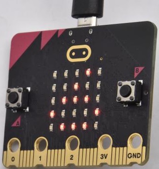
The LED dot matrix shows “TILT TO FILL SCREEN”. Pressing the button A, the board asks us to calibrate the compass. Then enter the calibration page. Rotate the board until all 25 red LEDs are on, as shown below.
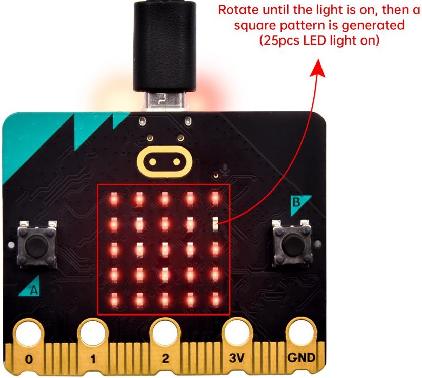
After that, a smile pattern  appears, which implies the calibration is done. When the calibration process is completed, pressing the button A will make the magnetometer reading display directly on the screen. And the direction north, east, south and west correspond to 0°, 90°, 180° and 270° respectively.
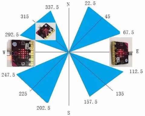
5. Test Code2
For the below picture, the arrow will work to point to the upper right when the value ranges from 292.5 to 337.5. Since 0.5 can’t be input in the code, the values we get are 293 and 338.
Then add other statements to make a set of complete code.
Enter Mu software and open the file“Magnetic sensor -2.py“ to import the code. You can also input code in the editing window yourself.
(Note: All words and symbols must be written in English.)
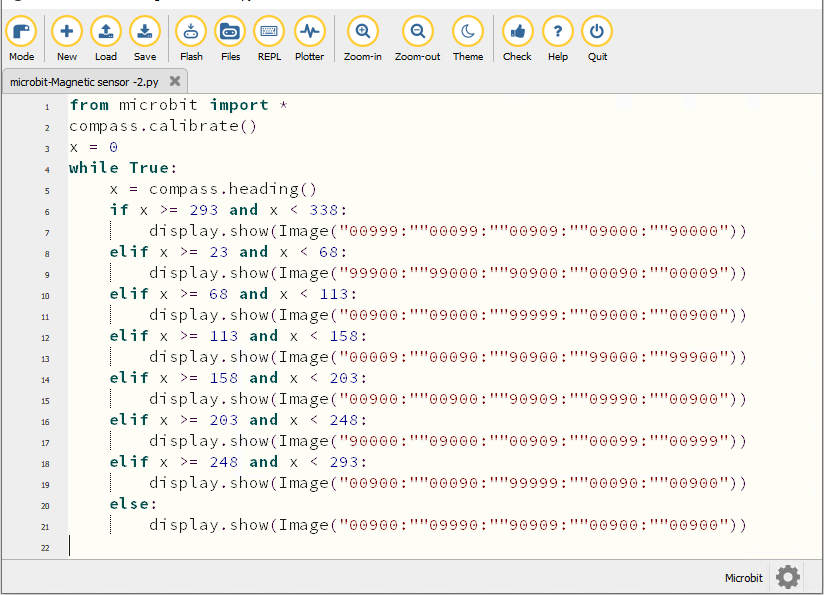
from microbit import *
compass.calibrate()
x = 0
while True:
    x = compass.heading()
    if x >= 293 and x < 338:
        display.show(Image("00999:""00099:""00909:""09000:""90000"))
    elif x >= 23 and x < 68:
        display.show(Image("99900:""99000:""90900:""00090:""00009"))
    elif x >= 68 and x < 113:
        display.show(Image("00900:""09000:""99999:""09000:""00900"))
    elif x >= 113 and x < 158:
        display.show(Image("00009:""00090:""90900:""99000:""99900"))
    elif x >= 158 and x < 203:
        display.show(Image("00900:""00900:""90909:""09990:""00900"))
    elif x >= 203 and x < 248:
        display.show(Image("90000:""09000:""00909:""00099:""00999"))
    elif x >= 248 and x < 293:
        display.show(Image("00900:""00090:""99999:""00090:""00900"))
    else:
        display.show(Image("00900:""09990:""90909:""00900:""00900"))
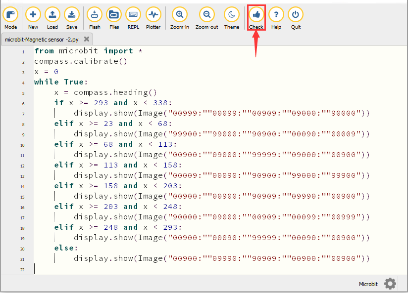
Click“Check”to examine errors in the code. The program proves wrong if underlines and cursors are shown.
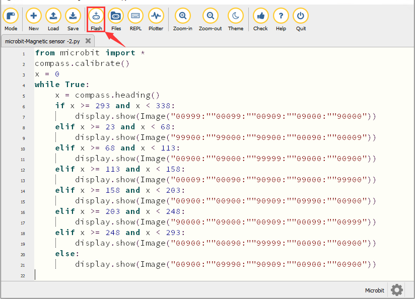
If the code is correct, connect the micro:bit to your computer and click“Flash”to download the code to the micro:bit board.
6. Test Result
After downloading the code to the board successfully, power on via micro USB cable or external power supply(turn the DIP switch to ON), and press the reset button on micro:bit.
After calibration, rotate the micro:bit board, then the LED dot matrix displays the direction signs.
7. Code Explanation
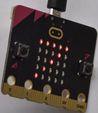
Project 7:Accelerometer
1. Description
The micro: bit main board V2 has a built-in LSM303AGR gravity acceleration sensor, also known as accelerometer, with a resolution of 8/10/12 bits. The code section sets the range to 1g, 2g, 4g, and 8g.
We often use an accelerometer to detect the status of machines.
In this project, we will work to introduce how to measure the position of the board with the accelerometer. And then have a look at the original three-axis data output by the accelerometer.
2. Preparation
A. Attach the micro:bit main board to your computer via the USB cable
B. Open the offline version of Mu.
3. Test Code1
Enter Mu software and open the file“Three-axis acceleration sensor -1.py“ to import the code. You can also input the code in the editing window yourself.
(Note: All words and symbols must be written in English.)
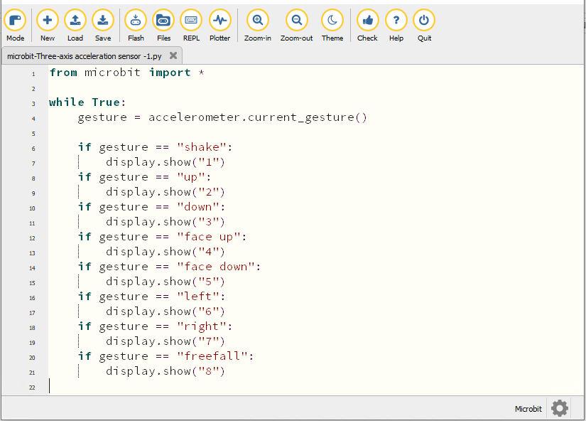
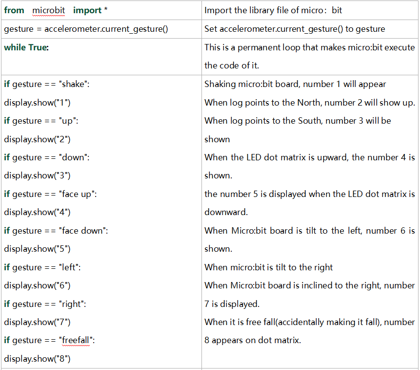
from microbit import *

while True:
    gesture = accelerometer.current_gesture()

    if gesture == "shake":
        display.show("1")
    if gesture == "up":
        display.show("2")
    if gesture == "down":
        display.show("3")
    if gesture == "face up":
        display.show("4")
    if gesture == "face down":
        display.show("5")
    if gesture == "left":
        display.show("6")
    if gesture == "right":
        display.show("7")
    if gesture == "freefall":
        display.show("8")
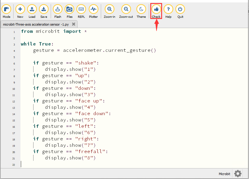
Click“Check”to examine errors in the code. The program proves wrong if underlines and cursors are shown.
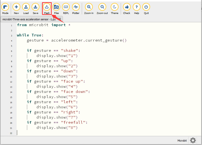
If the code is correct, connect the micro:bit to your computer and click“Flash”to download the code to the micro:bit board.
4. Test Result1
After downloading the code to the board successfully, power on via micro USB cable or external power supply(turn the DIP switch to ON), and press the reset button on micro:bit.
When we shake the micro: bit main board,no matter at any direction, the LED dot matrix displays the digit “1”.
When it is kept upright(make its logo above the LED dot matrix), the number 2 appears.
When it is kept upside down( make its logo below the LED dot matrix) , it shows as below.
When it is placed still on the desk, showing its front side, the number 4 appears.
When it is placed still on the desk, showing its back side, the number 5 exhibits.
When the board is tilted to the left , the LED dot matrix shows the number 6, as shown below:
When the board is tilted to the right , the LED dot matrix displays the number 7, as shown below:
When the board is knocked to the floor, this process can be considered as a free fall and the LED dot matrix shows the number 8. (Please note that this test is not recommended for it may damage the main board.)
Attention: If you’d like to try this function, you can also set the acceleration to 3g, 6g or 8g.
5. Test Code2
Enter Mu software and open the file“Three-axis acceleration sensor -2.py“ to import the code. You can also input the code in the editing window yourself.
(Note: All words and symbols must be written in English.)
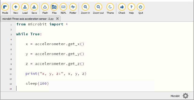
from microbit import *
while True:
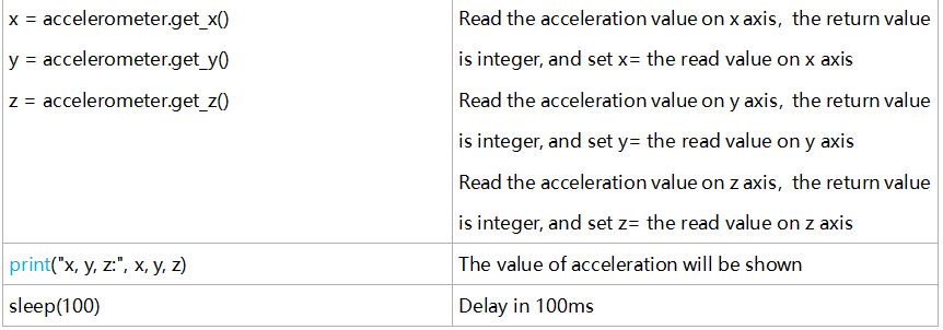
x = accelerometer.get_x()
y = accelerometer.get_y()
z = accelerometer.get_z()
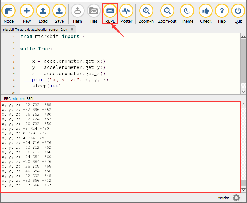
print("x, y, z:", x, y, z)
sleep(100)
Click“Check”to examine errors in the code. The program proves wrong if underlines and cursors are shown.
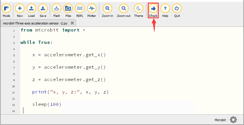
If the code is correct, connect the micro:bit to your computer and click“Flash”to download the code to the micro:bit board.
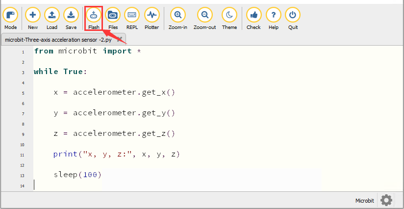
6. Test Result2
After downloading the code to the board successfully, power on via micro USB cable or external power supply(turn the DIP switch to ON). Click“REPL”and press the reset button on micro:bit.
Then REPL window will show the value of the acceleration on X axis, Y axis and Z axis are shown below:
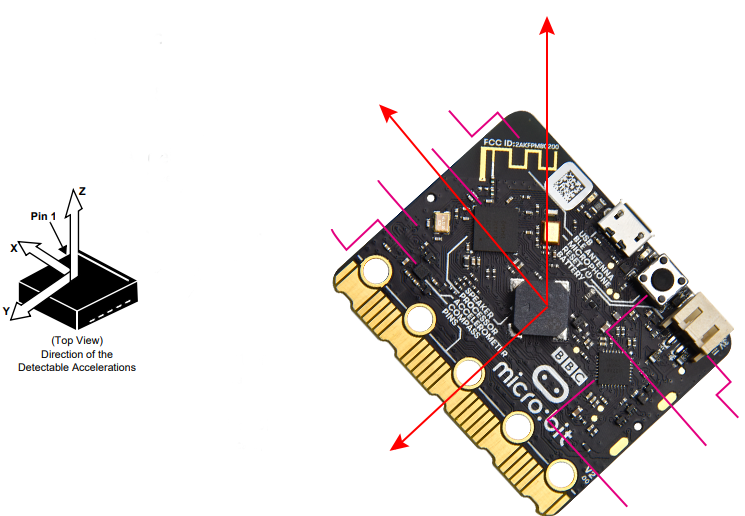
After referring to the MMA8653FC data manual and the hardware schematic diagram of the micro: bit main board, the accelerometer coordinate of the micro: bit is shown in the figure below:
7. Code Explanation
Project 8:Light Detection
1. Description
In this project, we will focus on the light detection function of the Micro: Bit main board. It is achieved by the LED dot matrix since the main board is not equipped with a photoresistor.
2. Preparation
A. Attach the micro:bit main board to your computer via the USB cable
B. Open the offline version of Mu.
3. Test Code
Enter Mu software and open the file“Detect Light Intensity by Microbit.py”to import the code. You can also input code in the edit window yourself.
(Note: All English words and symbols must be written in English.)
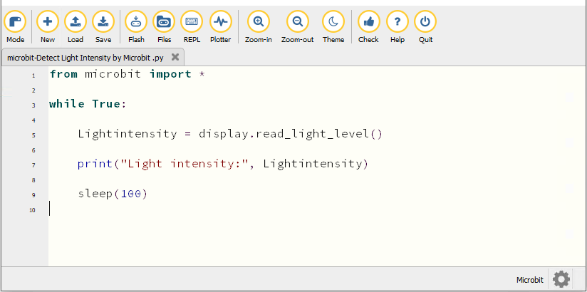
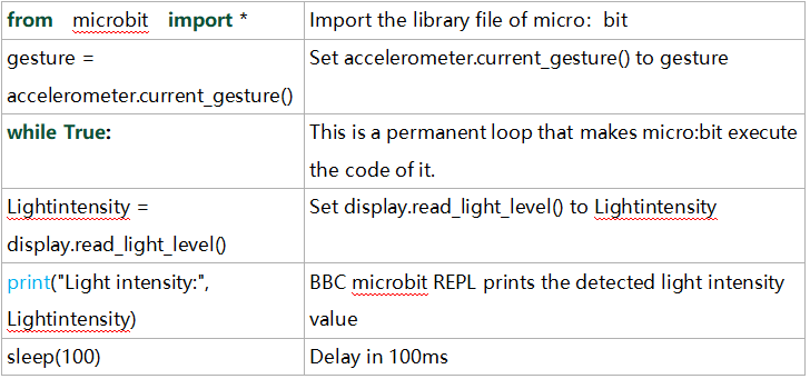
from microbit import *

while True:

    Lightintensity = display.read_light_level()

    print("Light intensity:", Lightintensity)

    sleep(100)
Click“Check”to examine errors in the code. The program proves wrong if underlines and cursors are shown.
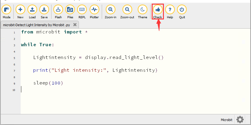
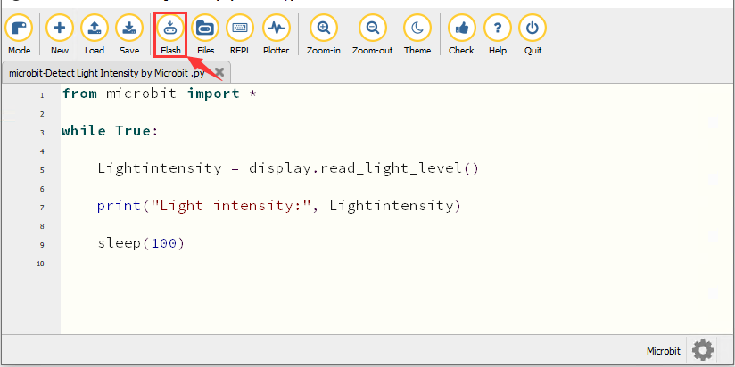
If the code is correct, connect the micro:bit to your computer and click“Flash”to download code to the micro:bit board.
4. Test Result
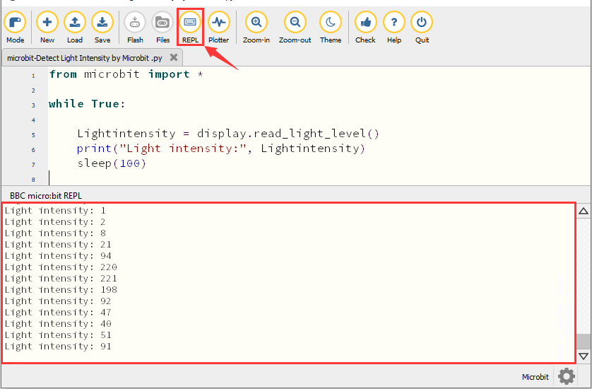
After downloading the code to the board successfully, power on via micro USB cable or external power supply(turn the DIP switch to ON). Click“REPL”and press the reset button on micro:bit.
Then REPL window will show the light intensity value, as shown below.
When the LED dot matrix is covered by hand, the light intensity showed is approximately 0; when the LED dot matrix is exposed to light, the light intensity displayed gets stronger with the light.
5. Code Explanation
Project 9:Speaker
1. Description
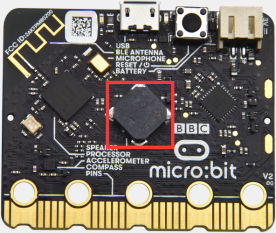
Micro: Bit main board has an built-in speaker, which makes adding sound to the programs easier. It can also be programmed to produce all kinds of tones, like playing the song Ode to Joy.
2. Preparation
A. Attach the micro:bit main board to your computer via the USB cable
B. Open the offline version of Mu.
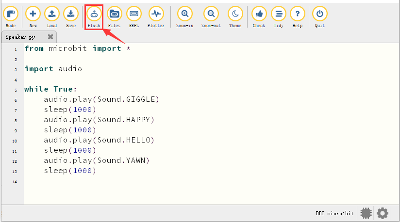
3. Test Code
Enter Mu software and open the file“Speaker.py”to import code. You can also input code in the editing window yourself.
(Note: All words and symbols must be written in English.)
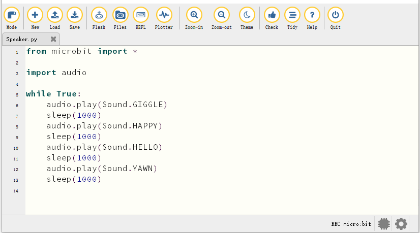
from microbit import *

import audio

display.show(Image.MUSIC_QUAVER)

while True:
    audio.play(Sound.GIGGLE)
    sleep(1000)
    audio.play(Sound.HAPPY)
    sleep(1000)
    audio.play(Sound.HELLO)
    sleep(1000)
    audio.play(Sound.YAWN)
    sleep(1000)
Click“Check”to examine errors in the code. The program proves wrong if underlines and cursors are shown.
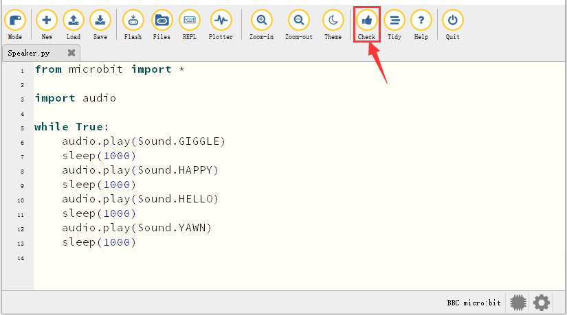
If the code is correct, connect the micro:bit to your computer and click“Flash”to download the code to the micro:bit board.
4. Test Result
After downloading the code to the board successfully, power on via micro USB cable or external power supply(turn the DIP switch to ON),and press the reset button on micro:bit.
The speaker utters sound and the LED dot matrix shows the logo of music.
5. Code Explanation
Project 10: Touch-sensitive Logo
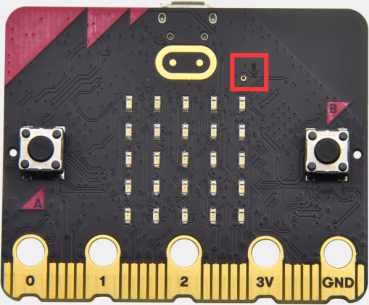
1. Description
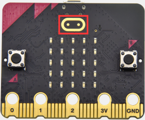
The Micro: Bit main board V2 is equipped with a golden touch-sensitive logo, which can act as an input component like an button.
It contains a capacitive touch sensor that senses small changes in the electric field when pressed (or touched), just like your phone or tablet screen. When you press it , the program can be activated.
2. Preparation
A. Attach the micro:bit main board to your computer via the USB cable
B. Open the offline version of Mu.
3. Test Code
Enter Mu software and open the file“Touch-sensitive Logo.py”to import code.You can also input code in the edit window yourself.
(Note: All English words and symbols must be written in English.)
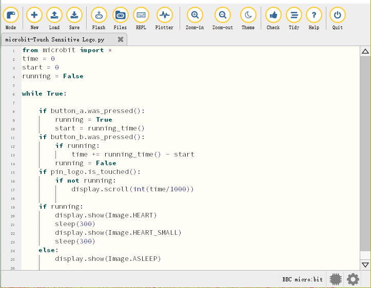
from microbit import *
time = 0
start = 0
running = False

while True:

    if button_a.was_pressed():
        running = True
        start = running_time()
    if button_b.was_pressed():
        if running:
            time += running_time() - start
        running = False
    if pin_logo.is_touched():
        if not running:
            display.scroll(int(time/1000))

    if running:
        display.show(Image.HEART)
        sleep(300)
        display.show(Image.HEART_SMALL)
        sleep(300)
    else:
        display.show(Image.ASLEEP)
How Micro:bit works?
A. The runtime is recorded in milliseconds(ms) .
B. When you press button A, a variable named start will be set to the current running time.
C. When you press button B, the start time will be subtracted from the new running time to calculate the passed time since you started the stopwatch. This difference is added to the total time, which is stored in a variable named time.
D. If you press the golden logo, the program will display the total elapsed time on the LED display. It converts time from milliseconds (thousandths of a second) to seconds by dividing by 1000. It uses the integer division operator to give an integer (integer) result.
E. The program is also controlled by a Boolean variable named running. Boolean variable only has two values: true or false. If “running” is “true”, it means that the stopwatch has started. If “running” is false, it means that the stopwatch has not started or has stopped.
F. If “running” is true, the beating heart pattern will be displayed on the LED dot matrix screen.
G. (7) If the stopwatch has stopped and the “running” is false, when you press the golden logo, it will only display the time.
H. If the stopwatch has been started and”running” is true, it only need to ensure that the time variable will change when button B is pressed, and the code can also prevent false readings.
Click“Check”to examine errors in the code. The program proves wrong if underlines and cursors are shown.
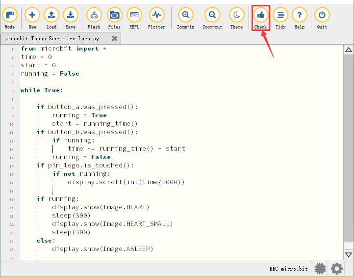
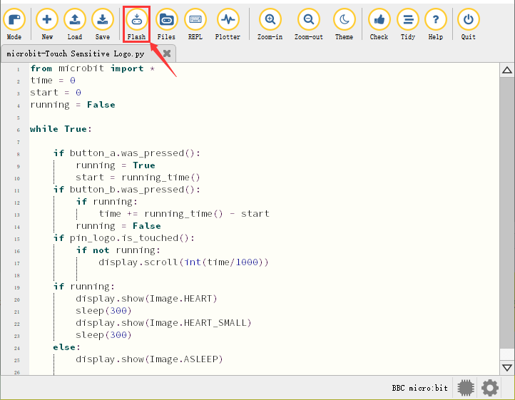
If the code is correct, connect the micro:bit to your computer and click“Flash”to download code to the micro:bit board.
4. Test Result
After downloading the code to the board successfully, power on via micro USB cable or external power supply(turn the DIP switch to ON),and press the reset button on micro:bit.
Press button A to start the stopwatch. When timing, the beating heart pattern will be displayed on the LED dot matrix screen. Press button B to stop it and you can start and stop it at any time.
It will keep recording time, just like a real stopwatch. Press the golden logo in the front of the micro:bit to display the measured time in seconds. And the time can be reset to zero by pressing the reset button on the back of it.
Project 11: Microphone
1. Description
The Micro: Bit main board has a built-in microphone, which can test the volume of ambient environment. When you clap, the microphone LED indicator turns on. Furthermore, it can measure the intensity of sound, thereby you can make a noise scale or disco lighting changing with music.
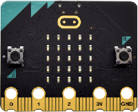
The microphone is placed on the opposite side of the microphone LED indicator and in proximity with holes that lets sound pass. When the board detects the sound, the LED indicator lights up.
2. Preparation
A. Attach the micro:bit main board to your computer via the USB cable
B. Open the offline version of Mu.
3. Test Code1
Enter Mu software and open the file“Microphone-1.py”to import the code. You can also input code in the editing window yourself.
(Note: All words and symbols must be written in English.)
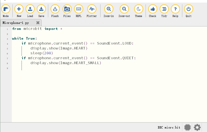
from microbit import *

while True:
    if microphone.current_event() == SoundEvent.LOUD:
        display.show(Image.HEART)
        sleep(200)
    if microphone.current_event() == SoundEvent.QUIET:
        display.show(Image.HEART_SMALL)
Click“Check”to examine errors in the code. The program proves wrong if underlines and cursors are shown.
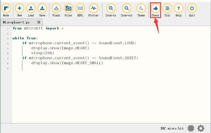
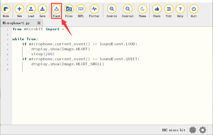
If the code is correct, connect the micro:bit to your computer and click“Flash”to download code to the micro:bit board.
4. Test Result1
After downloading the code to the board successfully, power on via micro USB cable or external power supply(turn the DIP switch to ON),and press the reset button on micro:bit.
The LED dot matrix displays the pattern “❤”when you clap and the pattern  when it is quiet around.
5. Test Code2
Enter Mu software and open the file“Microphone-2.py”to import the code. You can also input code in the editing window yourself.
(Note: All words and symbols must be written in English.)
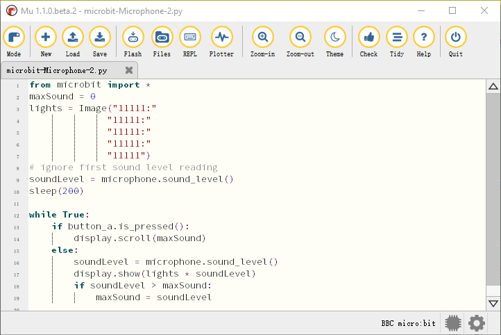
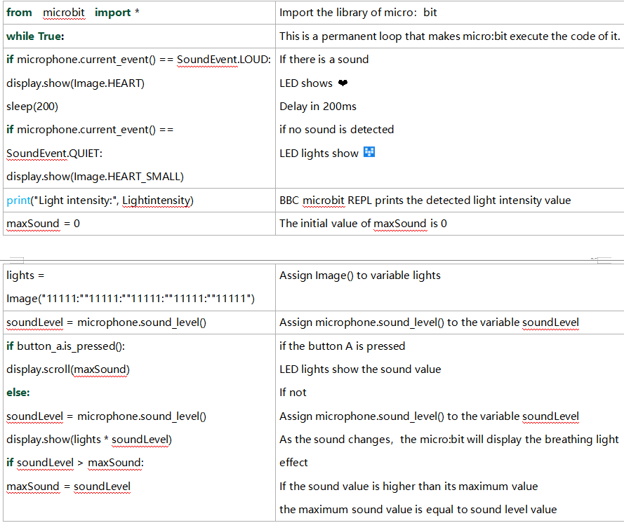
from microbit import *
maxSound = 0
lights = Image("11111:"
              "11111:"
              "11111:"
              "11111:"
              "11111")
# ignore first sound level reading
soundLevel = microphone.sound_level()
sleep(200)

while True:
    if button_a.is_pressed():
        display.scroll(maxSound)
    else:
        soundLevel = microphone.sound_level()
        display.show(lights * soundLevel)
        if soundLevel > maxSound:
            maxSound = soundLevel
Click“Check”to examine errors in the code. The program proves wrong if underlines and cursors are shown.
If the code is correct, connect the micro:bit to your computer and click“Flash”to download code to the micro:bit board.
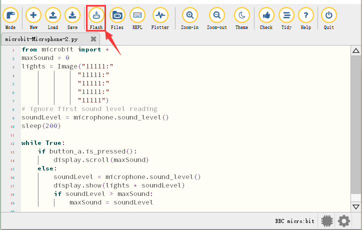
6. Test Result2
After downloading the code to the board successfully, power on via micro USB cable or external power supply(turn the DIP switch to ON),and press the reset button on micro:bit.
When the button A is pressed, the LED dot matrix displays the value of the biggest volume( please note that the biggest volume can be reset via the Reset button on the other side of the board ). When clapping, the louder the tested sound, the brighter the 25 LEDs on the LED dot matrix screen.
7. Code Explanation
Project 12: Control Speaker
1. Description
In the previous projects, we have learned about the touch-sensitive logo and the speaker respectively. In the project, we will combine these two components to play music.
2. Components Needed
|
|
|---|---|
Micro:bit main board *1 |
USB cable*1 |
3. Wiring Diagram
Attach the Micro:bit main board to your computer via the USB cable.
4. Test Code
Enter Mu software and open the file“Touch the Logo to control the speaker.py”to import code. You can also input code in the editing window yourself.
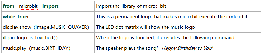
(Note: All words and symbols must be written in English.)
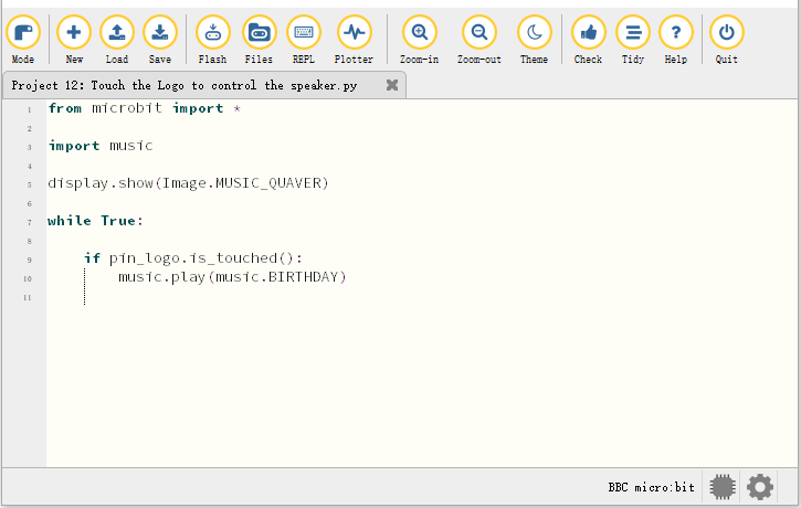
from microbit import *

import music

display.show(Image.MUSIC_QUAVER)

while True:

    if pin_logo.is_touched():
        music.play(music.BIRTHDAY)
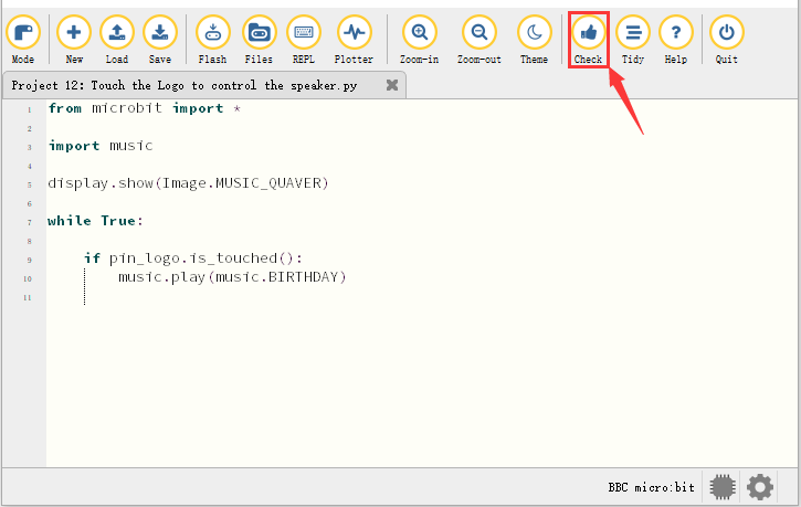
Click“Check”to examine errors in the code. The program proves wrong if underlines and cursors are shown.
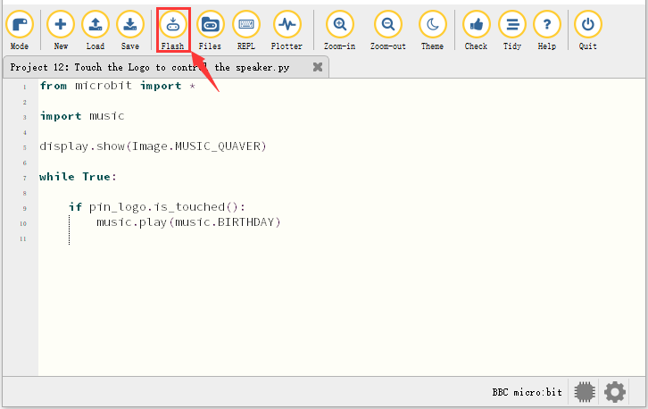
If the code is correct, connect the micro:bit to your computer and click“Flash”to download the code to the micro:bit board.
5. Test Result
After downloading the code to the board successfully, power on via micro USB cable or external power supply(turn the DIP switch to ON),and press the reset button on micro:bit.
The speaker plays the song “Happy Birthday to You” when the logo is touched.
6. Code Explanation
Bluetooth Wireless Communication
The micro:bit owns a low-consumption Bluetooth module to communicate but with 16k RAM. However, BLE heap stack occupies 12K RAM, thereby there is no enough space to run microPython.
At present, microPython doesn’t support the Bluetooth service.
https://microbit-micropython.readthedocs.io/en/latest/ble.html
The former projects are the introduction of sensors and modules. The further lessons are challenging for new starters.
(Note: In order to refrain the micro:bit board from being burned, disconnect the micro USB cable from it and turn off the power on the micro:bit motor driver base plate before installing it on the car expansion board and dial the POWER switch to the OFF end. Likewise, before removing the the main board from the car expansion board, disconnect the micro USB cable from it and turn off the power on the micro:bit motor driver base plate.)
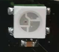
Project 13: Seven-Color LED
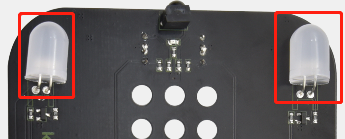
1. Description
This module consists of a commonly used LED with 7colors but in whit ppearance. It can automatically flash different colors to creat antastic light effects when high level is input like a normal LED.
2. Preparation
Insert the micro:bit board into the slot of keyestudio 4WD Mecanum Robot Car V2.0
Place batteries into battery holder
Dial power switch to ON end
Connect the micro:bit to your computer via an USB cable
Open the offline version of Mu.
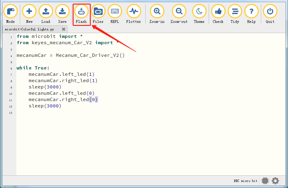
3. Test Code
Enter Mu software and open the file“Colorful lights.py”to import code. You can also input code in the editing window yourself.
(Note: All words and symbols must be written in English.)
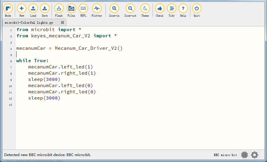
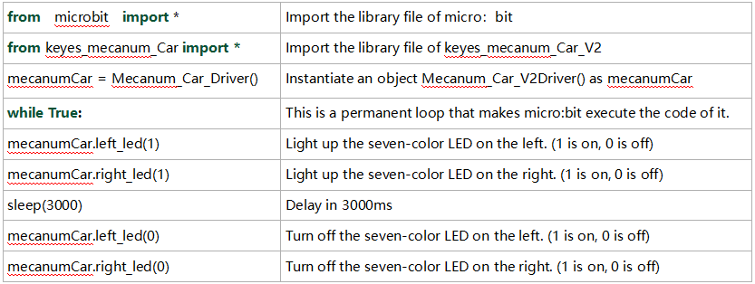
from microbit import *
from keyes_mecanum_Car_V2 import *

mecanumCar = Mecanum_Car_Driver_V2()

while True:
    mecanumCar.left_led(1)
    mecanumCar.right_led(1)
    sleep(3000)
    mecanumCar.left_led(0)
    mecanumCar.right_led(0)
    sleep(3000)
Important Notice: If the library file ‘keyes_mecanum_Car_V2.py’ has not yet been imported to the microbit board, it is essential to first import the library file to the microbit board. The method for importing the library can be found by clicking the link:How to Import Library to Micro:bit and following the instructions provided; otherwise, the code will not run.
After the library file is imported successfully, you also need to click the “Check” button to check the code. If a cursor or an underline appears on a certain line, then errors appear in the program.
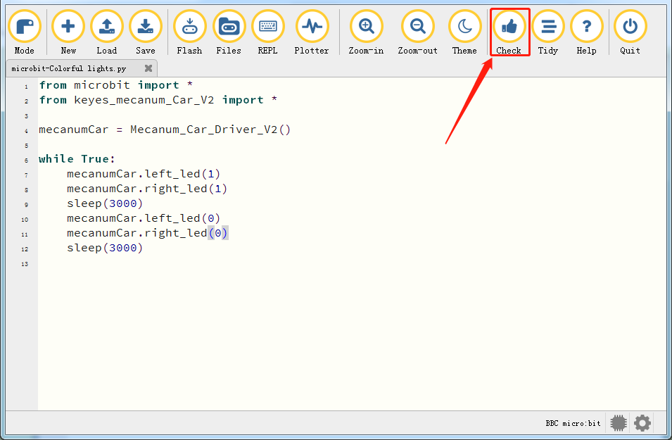
However, during this process, the following prompt will appear even if there is no error in the code. These prompts are just warnings not the code error prompts.


If the code is correct, connect the micro:bit to your computer and click“Flash”to download the code to the micro:bit board.
If errors appear after clicking the “Flash” button, please confirm whether you have imported the provided “keyes_mecanum_Car_V2.py” library file.
Note: Before programming with Micropython, you need to import the “keyes_mecanum_Car_V2.py” library file to the micro:bit. If you program with different micro:bit, the library file”keyes_mecanum_Car_V2.py” needs to be imported again to a new micro:bit.
4. Test Result
After downloading the code to the board successfully, external power supply(turn the DIP switch to ON),and press the reset button on micro:bit.
The seven-color LED will flash in 3s and then stop in 3s and repeat this pattern.
5. Code Explanation
Project 14: 4 WS2812 RGB LEDs
1. Description
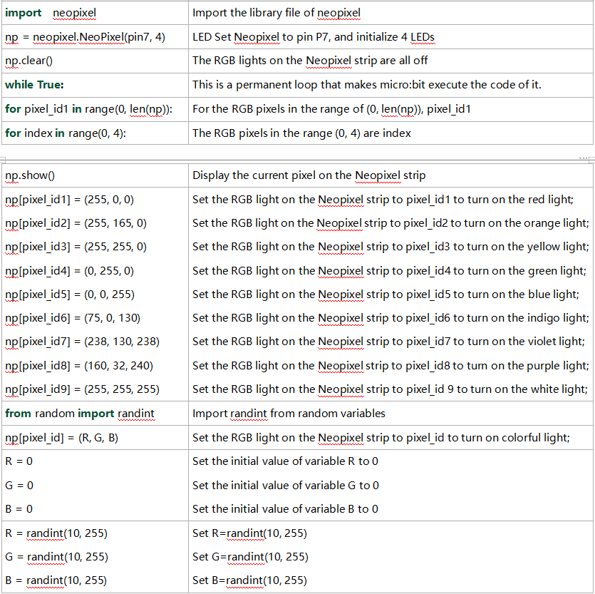
The driver shield cooperates 4 pcs WS2812 RGB LEDs, compatible with micro:bit board and controlled by P7. In this lesson, we will make the RGB LEDs display different colors by P7. In this lesson, 3 sets of test code are provided to make the 4 WS2812 RGB LEDs display different effects.
2. Preparation
Insert micro:bit board into the slot of keyestudio 4WD Mecanum Robot Car V2.0
Place batteries into battery holder
Dial power switch to ON end
Connect the micro:bit to your computer via an USB cable
Open the offline version of Mu.
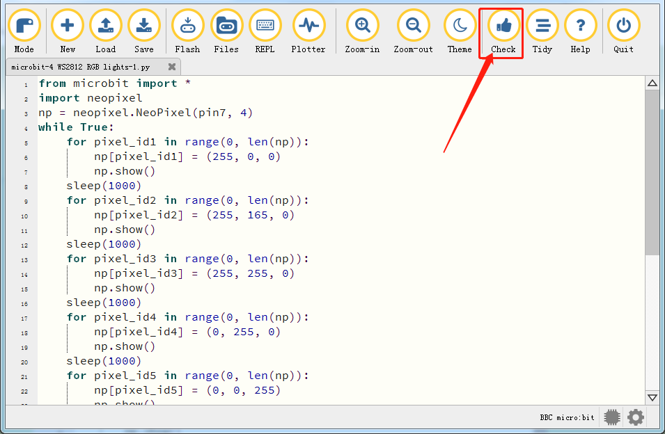
3. Test Code1
Enter Mu software and open the file“4 WS2812 RGB LEDs-1.py”to import code\ You can also input code in the edit window yourself.
(Note: All English words and symbols must be written in English.)
Click“Check”to examine errors in the code. The program proves wrong if underlines and cursors are shown.
from microbit import *
import neopixel
np = neopixel.NeoPixel(pin7, 4)
while True:
    for pixel_id1 in range(0, len(np)):
        np[pixel_id1] = (255, 0, 0)
        np.show()
    sleep(1000)
    for pixel_id2 in range(0, len(np)):
        np[pixel_id2] = (255, 165, 0)
        np.show()
    sleep(1000)
    for pixel_id3 in range(0, len(np)):
        np[pixel_id3] = (255, 255, 0)
        np.show()
    sleep(1000)
    for pixel_id4 in range(0, len(np)):
        np[pixel_id4] = (0, 255, 0)
        np.show()
    sleep(1000)
    for pixel_id5 in range(0, len(np)):
        np[pixel_id5] = (0, 0, 255)
        np.show()
    sleep(1000)
    for pixel_id6 in range(0, len(np)):
        np[pixel_id6] = (75, 0, 130)
        np.show()
    sleep(1000)
    for pixel_id7 in range(0, len(np)):
        np[pixel_id7] = (238, 130, 238)
        np.show()
    sleep(1000)
    for pixel_id8 in range(0, len(np)):
        np[pixel_id8] = (160, 32, 240)
        np.show()
    sleep(1000)
    for pixel_id9 in range(0, len(np)):
        np[pixel_id9] = (255, 255, 255)
    sleep(1000)
If the code is correct, connect the micro:bit to your computer and click“Flash”to download the code to the micro:bit board.
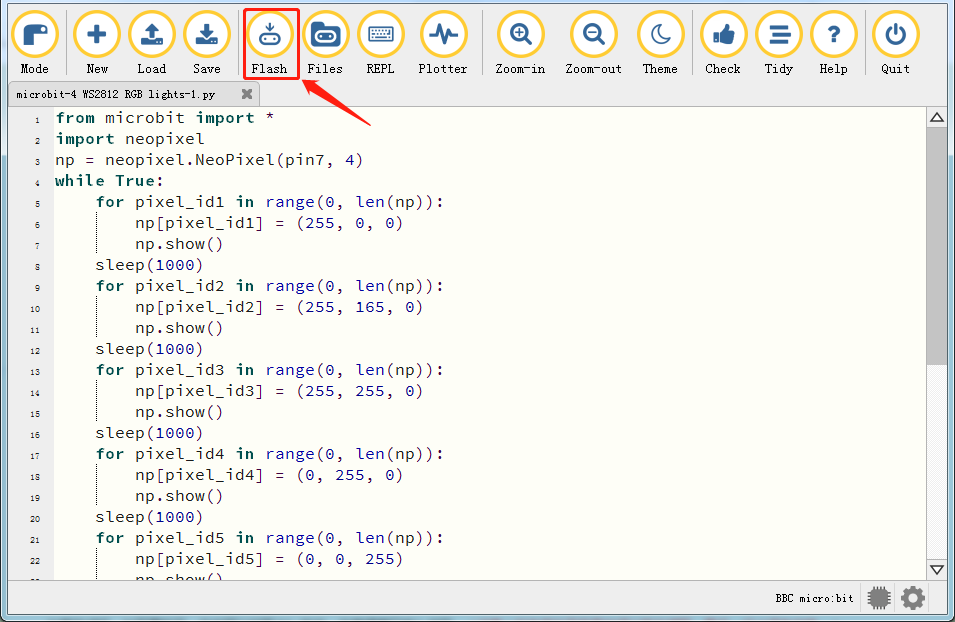
4. Test Result1
After downloading the code to the board successfully, external power supply(turn the DIP switch to ON),and press the reset button on micro:bit.
The 4 WS2812RGB LEDs light up a different color a time cyclically.
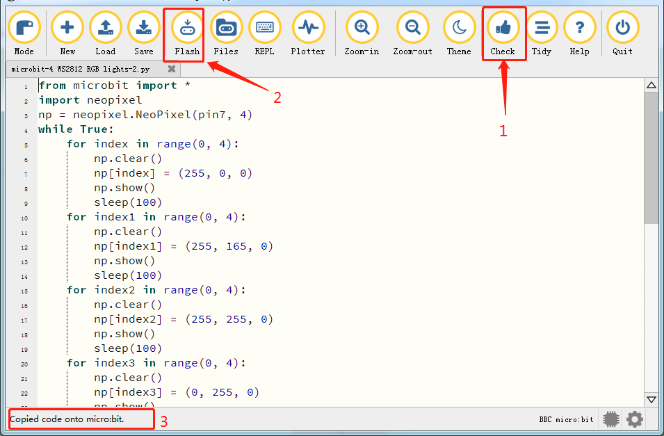
5. Test Code2
Enter Mu software and open the file“4 WS2812 RGB LEDs-2.py”to import code. You can also input code in the edit window yourself.
(Note: All English words and symbols must be written in English.)
Click“Check”to examine errors in the code. The program proves wrong if underlines and cursors are shown.
If the code is correct, connect the micro:bit to your computer and click“Flash”to download the code to the micro:bit board.
from microbit import *
import neopixel
np = neopixel.NeoPixel(pin7, 4)
while True:
    for index in range(0, 4):
        np.clear()
        np[index] = (255, 0, 0)
        np.show()
        sleep(100)
    for index1 in range(0, 4):
        np.clear()
        np[index1] = (255, 165, 0)
        np.show()
        sleep(100)
    for index2 in range(0, 4):
        np.clear()
        np[index2] = (255, 255, 0)
        np.show()
        sleep(100)
    for index3 in range(0, 4):
        np.clear()
        np[index3] = (0, 255, 0)
        np.show()
        sleep(100)
    for index4 in range(0, 4):
        np.clear()
        np[index4] = (0, 0, 255)
        np.show()
        sleep(100)
    for index5 in range(0, 4):
        np.clear()
        np[index5] = (75, 0, 130)
        np.show()
        sleep(100)
    for index6 in range(0, 4):
        np.clear()
        np[index6] = (238, 130, 238)
        np.show()
        sleep(100)
    for index7 in range(0, 4):
        np.clear()
        np[index7] = (160, 32, 240)
        np.show()
        sleep(100)
    for index8 in range(0, 4):
        np.clear()
        np[index8] = (255, 255, 255)
        np.show()
        sleep(100)
6. Test Result2
After downloading the code to the board successfully, external power supply(turn the DIP switch to ON),and press the reset button on micro:bit.
The WS2812RGB LEDs display like a flow light.
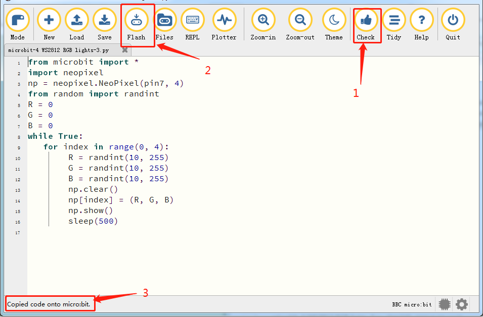
7. Test Code3
Enter Mu software and open the file“4 WS2812 RGB LEDs-3.py”to import code. You can also input code in the edit window yourself.
(Note: All English words and symbols must be written in English.)
Click“Check”to examine errors in the code. The program proves wrong if underlines and cursors are shown.
If the code is correct, connect the micro:bit to your computer and click“Flash”to download the code to the micro:bit board.
from microbit import *
import neopixel
np = neopixel.NeoPixel(pin7, 4)
from random import randint
R = 0
G = 0
B = 0
while True:
   for index in range(0, 4):
        R = randint(10, 255)
        G = randint(10, 255)
        B = randint(10, 255)
        np.clear()
        np[index] = (R, G, B)
        np.show()
        sleep(500)
8. Test Result3
After downloading the code to the board successfully, external power supply(turn the DIP switch to ON),and press the reset button on micro:bit.
Every WS2812RGB light shows random color one by one.
5. Code Explanation
Project 15:Servo
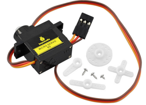
1. Description
The DIY smart cars usually contain the function of automatic obstacle avoidance. In the DIY process, we need a servo to control the ultrasonic module to rotate left and right, and then detect the distance between the car and the obstacle, so as to control the car to avoid the obstacle.
If other microcontrollers are used to control the rotation of the servo, we need to set a certain frequency and width of pulse to control the servo angle. But if the micro:bit main board is used to control the servo angle, we only need to set the control angle in the development environment where the corresponding pulse will be automatically set to control the servo rotation. In this project, you will learn how to control the servo to rotate back and forth between 0° and 90°.
Servo motor is a position control rotary actuator, which mainly consists of housing, circuit board, core-less motor, gear and position sensor. Its working principle is that the servo receives the signal sent by MCU or receiver, and produces a reference signal with a period of 20ms and width of 1.5ms, then compares the acquired DC bias voltage to the voltage of the potentiometer and obtains the voltage difference output.
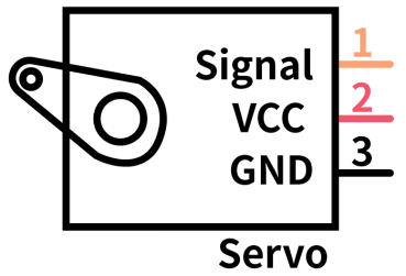
For the servo used in this project, the brown wire is the ground, the red one is the positive wire, and the orange one is the signal wire.
2. Information of the Servo
The rotation angle of servo motor is controlled by regulating the duty cycle of PWM (Pulse-Width Modulation) signal. The standard cycle of PWM signal is 20ms (50Hz). Theoretically, the width is distributed between 1ms-2ms, but in fact, it’s between 0.5ms-2.5ms. The width corresponds to the rotation angle from 0° to 180°. But note that for different brand motor, the same signal may have different rotation angle.
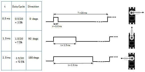
After measurement, the pulse range of the servo is 0.65ms~2.5ms. For a 180 degree servo, the corresponding control relationship is as follow:
Time on High Level |
Angle of the Servo |
Reference Signal Cycle Time(20ms) |
|---|---|---|
0.65ms |
0 degree |
0.65ms high level+19.35ms low level |
1.5ms |
90 degrees |
1.5ms high level+18.5ms low level |
2.5ms |
180degrees |
2.5ms high level+17.5ms low level |
3. Parameters
Working voltage: DC 4.8V ~ 6V
Operating angle range: about 180 ° (at 500 → 2500 μsec)
Dimension: 22.9*12.2*30mm
Pulse width range: 500 → 2500 μsec
No-load speed: 0.12 ± 0.01 sec / 60 (DC 4.8V), 0.1 ± 0.01 sec / 60 (DC 6V)
No-load current: 200 ± 20mA (DC 4.8V), 220 ± 20mA (DC 6V)
Stopping torque: 1.3 ± 0.01kg · cm (DC 4.8V) ,1.5 ± 0.1kg · cm (DC 6V)
Stop current: ≦ 850mA (DC 4.8V) ≦ 1000mA (DC 6V)
Standby current: 3 ± 1mA (DC 4.8V), 4 ± 1mA (DC 6V)
Weight: 9±1g (without servo horn)
Working temperature: -30℃~60℃
It should be noted that do not use a computer for power supply, because if the current demand is greater than 500mA, the servo may be burned out. It is recommended to use an external battery for power supply.
4. Preparation
Insert micro:bit board into the slot of keyestudio 4WD Mecanum Robot CarV2.0
Place batteries into battery holder
Dial power switch to ON end
Connect micro:bit to computer via an USB cable
Open the offline version of Mu.
5. Test Code
Enter Mu software and open the file“Servo.py”to import code. You can also input code in the edit window yourself.
(Note: All English words and symbols must be written in English.)
Click“Check”to examine errors in the code. The program proves wrong if underlines and cursors are shown.
If the code is correct, connect the micro:bit to your computer and click“Flash”to download the code to the micro:bit board.
from microbit import *

class Servo:
    def __init__(self, pin, freq=50, min_us=600, max_us=2400, angle=180):
        self.min_us = min_us
        self.max_us = max_us
        self.us = 0
        self.freq = freq
        self.angle = angle
        self.analog_period = 0
        self.pin = pin
        analog_period = round((1/self.freq) * 1000)  # hertz to miliseconds
        self.pin.set_analog_period(analog_period)

    def write_us(self, us):
        us = min(self.max_us, max(self.min_us, us))
        duty = round(us * 1024 * self.freq // 1000000)
        self.pin.write_analog(duty)
        sleep(100)
        self.pin.write_analog(0)

    def write_angle(self, degrees=None):
        if degrees is None:
            degrees = math.degrees(radians)
        degrees = degrees % 360
        total_range = self.max_us - self.min_us
        us = self.min_us + total_range * degrees // self.angle
        self.write_us(us)

Servo(pin14).write_angle(0)
display.show(Image.HAPPY)

while True:
        Servo(pin14).write_angle(0)
        sleep(1000)
        Servo(pin14).write_angle(45)
        sleep(1000)
        Servo(pin14).write_angle(90)
        sleep(1000)
        Servo(pin14).write_angle(135)
        sleep(1000)
        Servo(pin14).write_angle(180)
        sleep(1000)
4. Test Result
After downloading the code to the board successfully, external power supply(turn the DIP switch to ON),and press the reset button on micro:bit.
The LED dot matrix shows a smiley pattern and the servo rotates in the pattern 0°~45°~90°~135°~180°~0°.
Project 16:Motor
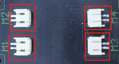
1. Description
The Keyestudio 4WD Mecanum Robot Car is equipped with 4 DC reduction motors, also called gear reduction motor, which is developed on the ordinary DC motor. It has a matching gear reduction box which provides a lower speed but a larger torque. Furthermore, different reduction ratios of the box can provide different speeds and torques.
Gear motor is the integration of gearmotor and motor, which is applied widely in steel and machine industry
Micro:bit motor driver shield comes with a STC8G and HR8833 chip. In order to save the IO port resource, we control the rotation direction and speed of 4 DC gear motors with the HR8833 chip.
Details about chips:
Front
Back
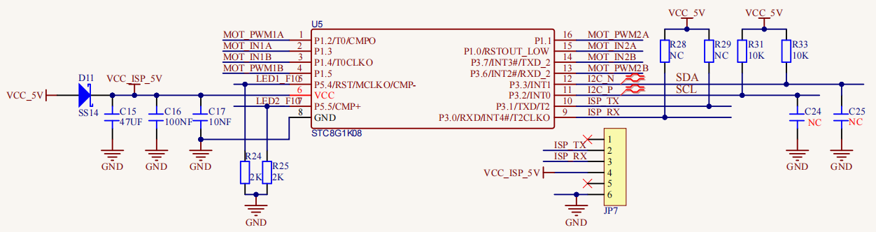
STC8G1K08 Chip circuit
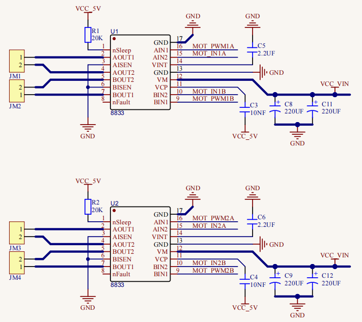
HR8833 Motor driver circuit
2. Preparation
Insert micro:bit board into the slot of keyestudio 4WD Mecanum Robot CarV2.0
Place batteries into battery holder
Dial power switch to ON end
Connect micro:bit to the computer via an USB cable
Open the offline version of Mu.
3. Test Code1
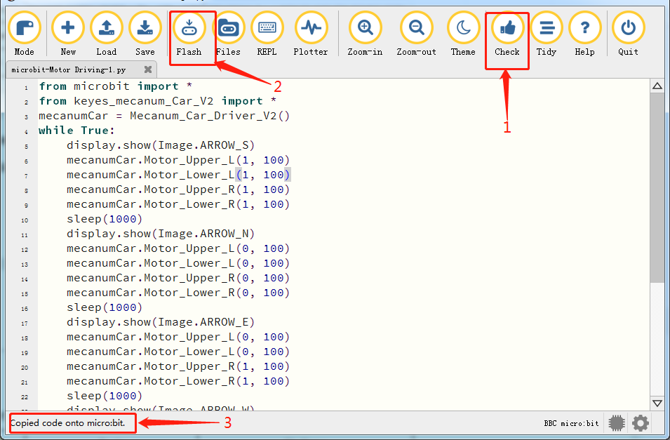
Enter Mu software and open the file“microbit-Motor Driving-1.py”to import code. You can also input code in the edit window yourself.
(Note: All English words and symbols must be written in English.)
Click“Files”to import“keyes_mecanum_Car.py”library file to micro:bit .
Click“Check”to examine errors in the code. The program proves wrong if underlines and cursors are shown.
If the code is correct, connect the micro:bit to your computer and click“Flash”to download the code to the micro:bit board.
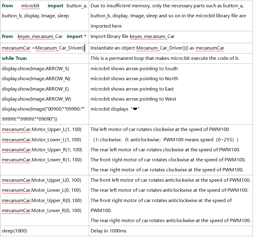
from microbit import *
from keyes_mecanum_Car_V2 import *
mecanumCar = Mecanum_Car_Driver_V2()
while True:
    display.show(Image.ARROW_S)
    mecanumCar.Motor_Upper_L(1, 100)
    mecanumCar.Motor_Lower_L(1, 100)
    mecanumCar.Motor_Upper_R(1, 100)
    mecanumCar.Motor_Lower_R(1, 100)
    sleep(1000)
    display.show(Image.ARROW_N)
    mecanumCar.Motor_Upper_L(0, 100)
    mecanumCar.Motor_Lower_L(0, 100)
    mecanumCar.Motor_Upper_R(0, 100)
    mecanumCar.Motor_Lower_R(0, 100)
    sleep(1000)
    display.show(Image.ARROW_E)
    mecanumCar.Motor_Upper_L(0, 100)
    mecanumCar.Motor_Lower_L(0, 100)
    mecanumCar.Motor_Upper_R(1, 100)
    mecanumCar.Motor_Lower_R(1, 100)
    sleep(1000)
    display.show(Image.ARROW_W)
    mecanumCar.Motor_Upper_L(1, 100)
    mecanumCar.Motor_Lower_L(1, 100)
    mecanumCar.Motor_Upper_R(0, 100)
    mecanumCar.Motor_Lower_R(0, 100)
    sleep(1000)
    display.show(Image("00900:""09990:""99999:""99999:""09090"))
    mecanumCar.Motor_Upper_L(0, 0)
    mecanumCar.Motor_Lower_L(0, 0)
    mecanumCar.Motor_Upper_R(0, 0)
    mecanumCar.Motor_Lower_R(0, 0)
    sleep(1000)
4. Test Result1
After downloading the code to the board successfully, external power supply(turn the DIP switch to ON),and press the reset button on micro:bit.
Then the car will go forward for 1s, back for 1s, turn left for 1s, right for 1s, turn anticlockwise for 1s, clockwise for 1 and stop 1s. Matrix also displays the patterns.
5. Test Code2
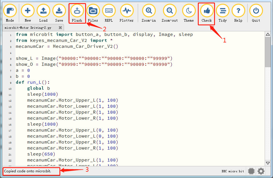
Enter Mu software and open the file“microbit-Motor Driving-2.py”to import code. You can also input code in the edit window yourself.
(Note: All English words and symbols must be written in English.)
Click“Files”to import“keyes_mecanum_Car.py“library file to micro:bit.
Click“Check”to examine errors in the code. The program proves wrong if underlines and cursors are shown.
If the code is correct, connect the micro:bit to your computer and click“Flash”to download the code to the micro:bit board.
from microbit import button_a, button_b, display, Image, sleep
from keyes_mecanum_Car_V2 import *
mecanumCar = Mecanum_Car_Driver_V2()
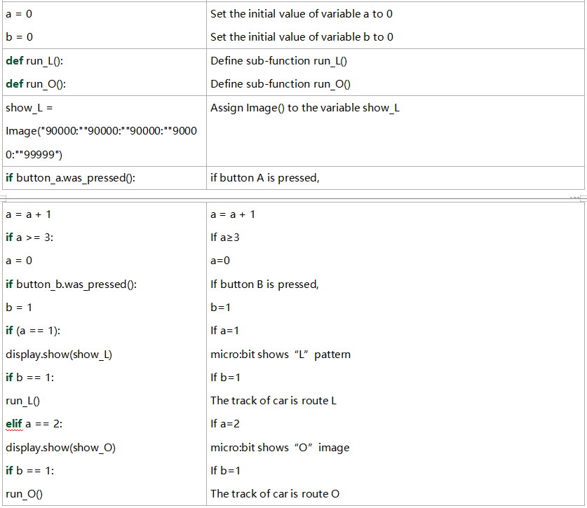
show_L = Image("90000:""90000:""90000:""90000:""99999")
show_O = Image("09990:""90009:""90009:""90009:""09990")
a = 0
b = 0
def run_L():
global b
sleep(1000)
mecanumCar.Motor_Upper_L(1, 100)
mecanumCar.Motor_Lower_L(1, 100)
mecanumCar.Motor_Upper_R(1, 100)
mecanumCar.Motor_Lower_R(1, 100)
sleep(1000)
mecanumCar.Motor_Upper_L(0, 100)
mecanumCar.Motor_Lower_L(0, 100)
mecanumCar.Motor_Upper_R(1, 100)
mecanumCar.Motor_Lower_R(1, 100)
sleep(650)
mecanumCar.Motor_Upper_L(1, 100)
mecanumCar.Motor_Lower_L(1, 100)
mecanumCar.Motor_Upper_R(1, 100)
mecanumCar.Motor_Lower_R(1, 100)
sleep(1000)
mecanumCar.Motor_Upper_L(0, 0)
mecanumCar.Motor_Lower_L(0, 0)
mecanumCar.Motor_Upper_R(0, 0)
mecanumCar.Motor_Lower_R(0, 0)
b = 0
def run_O():
global b
sleep(1000)
mecanumCar.Motor_Upper_L(1, 100)
mecanumCar.Motor_Lower_L(1, 100)
mecanumCar.Motor_Upper_R(1, 100)
mecanumCar.Motor_Lower_R(1, 100)
sleep(1000)
mecanumCar.Motor_Upper_L(0, 100)
mecanumCar.Motor_Lower_L(0, 100)
mecanumCar.Motor_Upper_R(1, 100)
mecanumCar.Motor_Lower_R(1, 100)
sleep(620)
mecanumCar.Motor_Upper_L(1, 100)
mecanumCar.Motor_Lower_L(1, 100)
mecanumCar.Motor_Upper_R(1, 100)
mecanumCar.Motor_Lower_R(1, 100)
sleep(1000)
mecanumCar.Motor_Upper_L(0, 100)
mecanumCar.Motor_Lower_L(0, 100)
mecanumCar.Motor_Upper_R(1, 100)
mecanumCar.Motor_Lower_R(1, 100)
sleep(620)
mecanumCar.Motor_Upper_L(1, 100)
mecanumCar.Motor_Lower_L(1, 100)
mecanumCar.Motor_Upper_R(1, 100)
mecanumCar.Motor_Lower_R(1, 100)
sleep(1000)
mecanumCar.Motor_Upper_L(0, 100)
mecanumCar.Motor_Lower_L(0, 100)
mecanumCar.Motor_Upper_R(1, 100)
mecanumCar.Motor_Lower_R(1, 100)
sleep(620)
mecanumCar.Motor_Upper_L(1, 100)
mecanumCar.Motor_Lower_L(1, 100)
mecanumCar.Motor_Upper_R(1, 100)
mecanumCar.Motor_Lower_R(1, 100)
sleep(1000)
mecanumCar.Motor_Upper_L(0, 0)
mecanumCar.Motor_Lower_L(0, 0)
mecanumCar.Motor_Upper_R(0, 0)
mecanumCar.Motor_Lower_R(0, 0)
b = 0
while True:
if button_a.was_pressed():
a = a + 1
if a >= 3:
a = 0
if button_b.was_pressed():
b = 1
if (a == 1):
display.show(show_L)
if b == 1:
run_L()
elif a == 2:
display.show(show_O)
if b == 1:
run_O()
6. Test Result2
After downloading the code to the board successfully, external power supply(turn the DIP switch to ON),and press the reset button on micro:bit.
When the button A and B are firstly pressed, micro:bit will show “L”, the route of the car is“L”. When they are pressed again,“口”is shown on micro:bit, and route of the car is“口”. The car will repeat this pattern.
7. Code Explanation
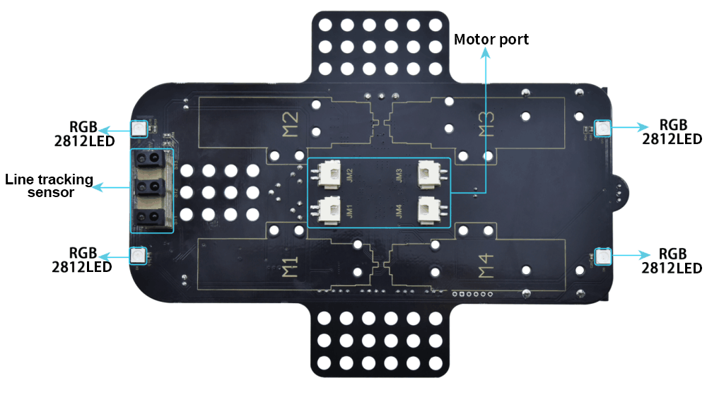
Project 17:Line Tracking Sensor
Project 17.1:Detect Line Tracking Sensor
1. Description
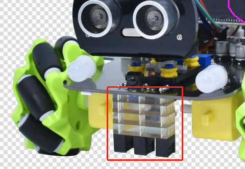
The motor driver board of the Keyestudio 4WD Mecanum Robot Car comes with a 3-channel line tracking sensor, which adopts TCRT5000 IR tubes and 3 potentiometers.
The TCRT5000 IR tube contains an IR emitting tube and an IR receiving tube. When the infrared signals of the emitting tube is received by the receiving tube through reflection, the resistance of the receiving tube will change, which is generally reflected in the voltage change on the circuit.
The resistance varies depending on the intensity of the infrared signals received by the receiving tube, which is often in the color of the reflecting surface and the distance of the reflecting surface receiving tube. At the time of detection, black is high level active and white is low level active.
2. Working Principle
When the car runs above a white road, the IR emitting tube installed under the car emits infrared signals to detect the road and the receiving tube will receive signals sending back. Then the output end outputs low level(0); when it detects black lines, it outputs high level(1).
The 3-channel tracking sensor integrated port on the 4WD Mecanum Robot Car is connected to the collection port of G ,5V ,P10, P4 and P3 on the micro:bit expansion board, which is controlled by the P10, P4 and P3 of the micro:bit. The left TCRT5000 infrared pair tube on the sensor is controlled by P3, the middle one is by P4 and the right one is by P10.
After putting a white paper on the bottom of the 4WD Mecanum Robot Car, we will rotate the potentiometers on the 3-way tracking sensor. When the indicator light on the sensor module is on, pick up the car to make the two wheels on the 4WD Mecanum Robot Car separate. The height of the white paper is about 1.5cm, when the indicator light on the sensor module is off, and then the sensitivity is adjusted.
**Note that since the 5*5 dot matrix uses the P3P4P6P7P10, we must turn off the dot matrix function when using the line tracking sensor. **
3. Preparation
Insert micro:bit board into the slot of keyestudio 4WD Mecanum Robot CarV2.0
Place batteries into battery holder
Dial power switch to ON end
Connect micro:bit to computer via an USB cable
Open the offline version of Mu.
4. Test Code
Enter Mu software and open the file“Line tracking detection.py”to import code. You can also input code in the edit window yourself.
(Note: All English words and symbols must be written in English.)
Click“Check”to examine errors in the code. The program proves wrong if underlines and cursors are shown.
If the code is correct, connect the micro:bit to your computer and click“Flash”to download the code to the micro:bit board.
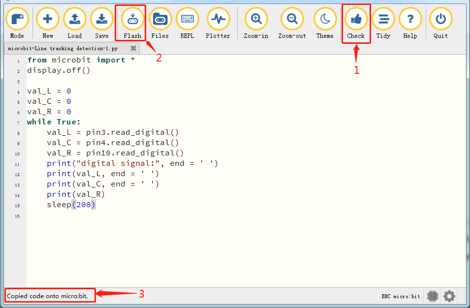
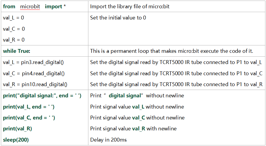
from microbit import *
display.off()

val_L = 0
val_C = 0
val_R = 0
while True:
    val_L = pin3.read_digital()
    val_C = pin4.read_digital()
    val_R = pin10.read_digital()
    print("digital signal:", end = ' ')
    print(val_L, end = ' ')
    print(val_C, end = ' ')
    print(val_R)
    sleep(200)
5. Test Result
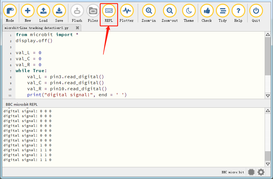
After downloading the code to the board successfully and don’t plug off the USB cable. Click“REPL”and then press the reset button.
The readings detected by the left TCRT5000 IR tube will be displayed on monitor.
When the left TCRT5000 IR tube detects the white object, 0 will be shown and the left indicator will be on; when there is only black object detected, 1 will be displayed and the indicator will be off, as shown below:
6. Code Explanation
Project 17.2:Tracking Smart Car
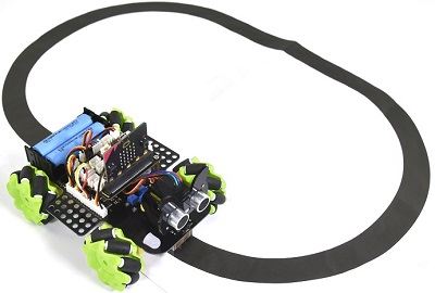
1. Description
In this lesson we will combine a line tracking sensor with a motor to make a line tracking smart car.
The micro:bit board will analyze the signals and control the smart car to show the line tracking function.
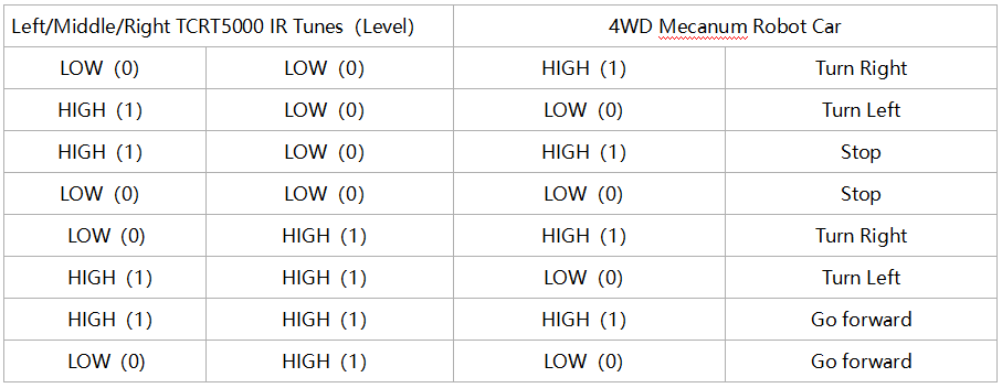
2. Working Principle
The smart car will make different moves according to the value received by the 3-channel line tracking sensor.
3. Preparation
Insert micro:bit board into the slot of keyestudio 4WD Mecanum Robot CarV2.0
Place batteries into battery holder
Dial power switch to ON end
Connect micro:bit to computer via an USB cable
Open the offline version of Mu.
Warning: The 3-way tracking sensor should be used in environment without infrared interference such as sunlight. Sunlight contains a lot 0f invisible light, such as infrared and ultraviolet. In an environmen with strong sunlight, the 3-way tracking sensor cannot work properly.
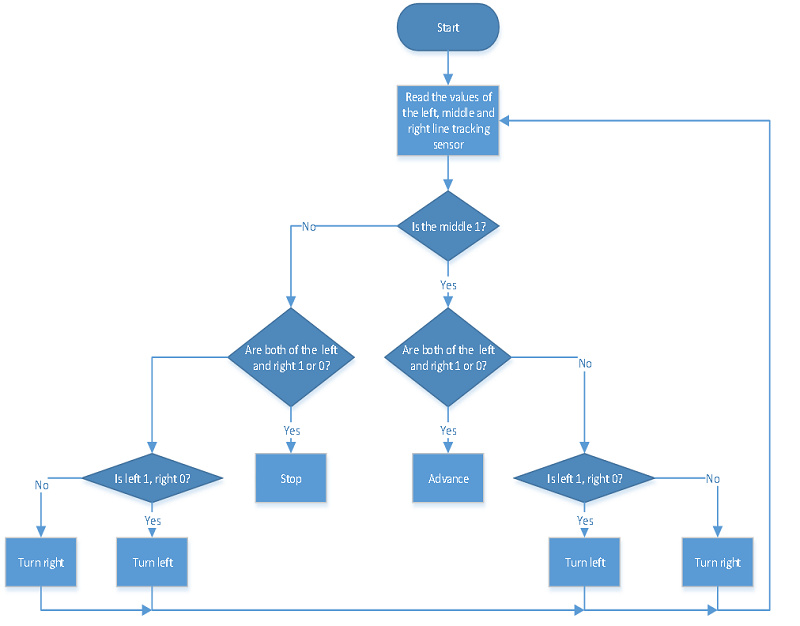
4. Flow Chart
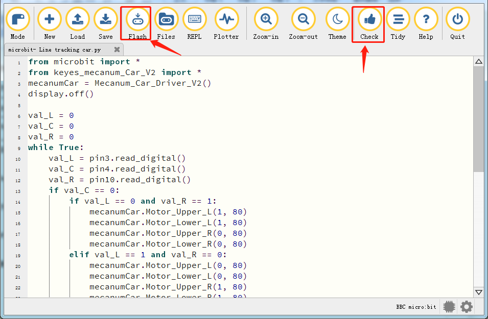
5. Test Code
Enter Mu software and open the file“Line tracking car.py”to import code. You can also input code in the edit window yourself.
(Note: All English words and symbols must be written in English.)
Click“Files”to import“keyes_mecanum_Car.py”library file to micro:bit.
Click“Check”to examine errors in the code. The program proves wrong if underlines and cursors are shown.
If the code is correct, connect the micro:bit to your computer and click“Flash”to download the code to the micro:bit board.
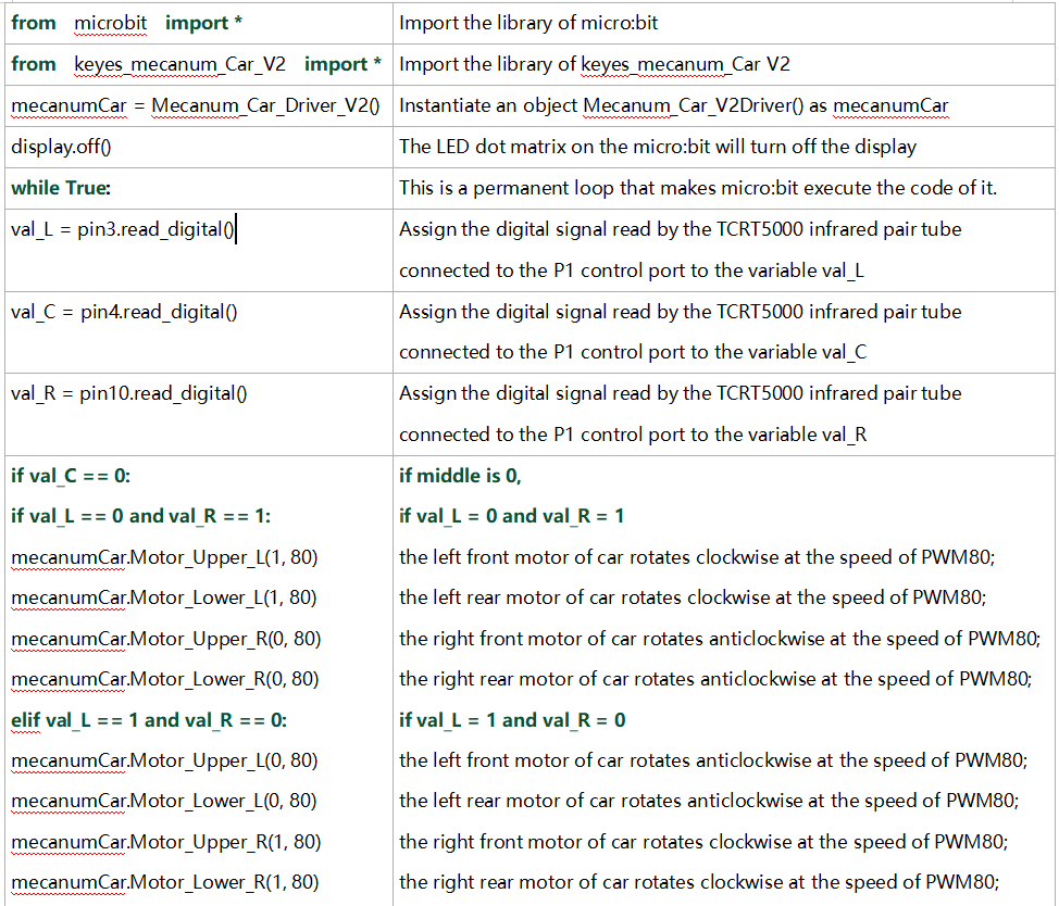
from microbit import *
from keyes_mecanum_Car_V2 import *
mecanumCar = Mecanum_Car_Driver_V2()
display.off()
val_L = 0
val_C = 0
val_R = 0
while True:
val_L = pin3.read_digital()
val_C = pin4.read_digital()
val_R = pin10.read_digital()
if val_C == 0:
if val_L == 0 and val_R == 1:
mecanumCar.Motor_Upper_L(1, 80)
mecanumCar.Motor_Lower_L(1, 80)
mecanumCar.Motor_Upper_R(0, 80)
mecanumCar.Motor_Lower_R(0, 80)
elif val_L == 1 and val_R == 0:
mecanumCar.Motor_Upper_L(0, 80)
mecanumCar.Motor_Lower_L(0, 80)
mecanumCar.Motor_Upper_R(1, 80)
mecanumCar.Motor_Lower_R(1, 80)
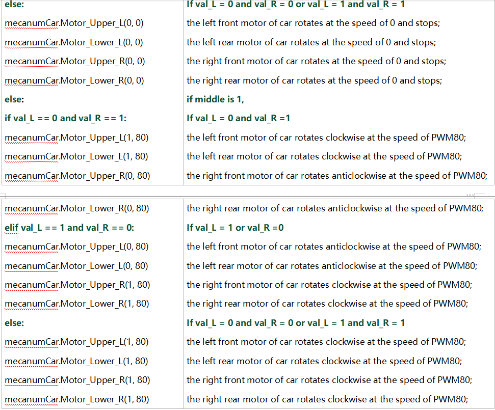
else:
mecanumCar.Motor_Upper_L(0, 0)
mecanumCar.Motor_Lower_L(0, 0)
mecanumCar.Motor_Upper_R(0, 0)
mecanumCar.Motor_Lower_R(0, 0)
else :
if val_L == 0 and val_R == 1:
mecanumCar.Motor_Upper_L(1, 80)
mecanumCar.Motor_Lower_L(1, 80)
mecanumCar.Motor_Upper_R(0, 80)
mecanumCar.Motor_Lower_R(0, 80)
elif val_L == 1 and val_R == 0:
mecanumCar.Motor_Upper_L(0, 80)
mecanumCar.Motor_Lower_L(0, 80)
mecanumCar.Motor_Upper_R(1, 80)
mecanumCar.Motor_Lower_R(1, 80)
else:
mecanumCar.Motor_Upper_L(1, 80)
mecanumCar.Motor_Lower_L(1, 80)
mecanumCar.Motor_Upper_R(1, 80)
mecanumCar.Motor_Lower_R(1, 80)
6. Test Result
After downloading the code to the board successfully, external power supply(turn the DIP switch to ON),and press the reset button on micro:bit.
The line tacking car goes forward along the black line .
Note: (1)The width of black line should be equal to or larger than the width of the line tracking sensor when tracking.
(2)Avoid to test the smart car under the strong light.
7. Code Explanation
Project 18:Ultrasonic Sensor
Project 18.1:Ultrasonic Ranging
1. Description
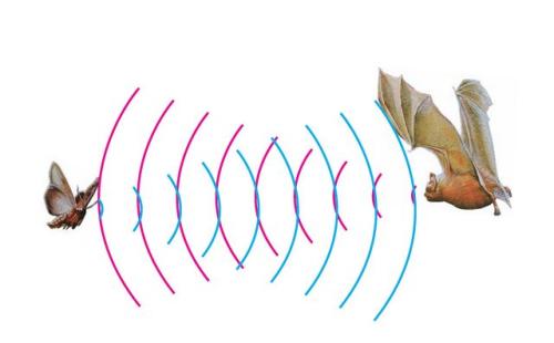
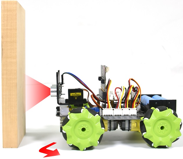
The ultrasonic sensor uses sonar to determine distance to an object like bats do. It offers excellent non-contact range detection with high accuracy and stable readings in an easy-to-use package. It comes complete with ultrasonic transmitter and receiver modules.
The ultrasonic sensor is being used in a wide range of electronics projects for creating obstacle detection and distance measuring application as well as various other applications.
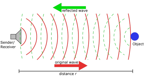
The ultrasonic module will emit the ultrasonic waves after trigger signals. When the ultrasonic waves encounter the object and are reflected back, the module outputs an echo signal, so it can determine the distance of object from the time difference between trigger signal (TRIG)and echo signal(ECHO).
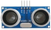
As the picture shows, it is like two eyes. One is transmitting end, the other is receiving end.
According to the above wiring diagram, the integrated port of the ultrasonic sensor module is connected to the 5V G P15 P16 port on the micro:bit motor driver base plate. The Trig (T) pin is controlled by P15 of the micro:bit and the pin of Echo (E) the P16.
2. Working Principle
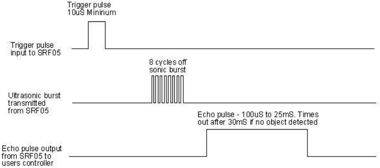
(1)Pull down TRIG then trigger high level signals with least 10us;
(2)After triggering, the module will automatically send eight 40KHz ultrasonic pulses and detect whether there is a signal return;
(3)If there is a signal return, when ECHO (E) outputs a high level, then the duration of the high level is the time from transmission to reception of the ultrasonic waves. Then test distance = high level duration *340m/s*0.5.
3. Parameters
Working voltage: 3-5.5V (DC)
Working current: 15mA
Working frequency: 40khz
Maximum detection distance: about 3m
Minimum detection distance: 2-3cm
Precision: up to 0.2cm
Sensing angle: less than 15 degrees
Input trigger pulse: 10us TTL level
Output echo signal: output TTL level signal (high), proportional t range
4. Preparation
Insert micro:bit board into the slot of keyestudio 4WD Mecanum Robot CarV2.0
Place batteries into battery holder
Dial power switch to ON end
Connect micro:bit to the computer via an USB cable
Open the offline version of Mu.
5. Test Code
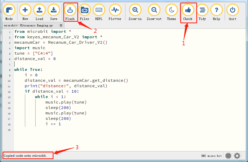
Enter Mu software and open the file“Ultrasonic Ranging.py”to import code. You can also input code in the edit window yourself.
(Note: All English words and symbols must be written in English.)
Click“Files”to import“keyes_mecanum_Car_V2.py“library file to micro:bit.
Click“Check”to examine errors in the code. The program proves wrong if underlines and cursors are shown.
If the code is correct, connect the micro:bit to your computer and click“Flash”to download the code to the micro:bit board.
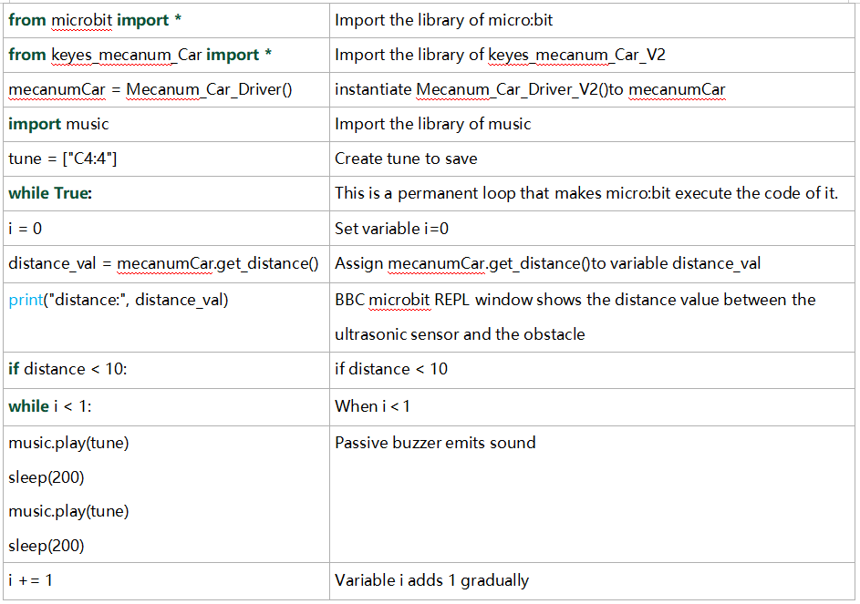
from microbit import *
from keyes_mecanum_Car_V2 import *
mecanumCar = Mecanum_Car_Driver_V2()
import music
tune = ["C4:4"]
distance_val = 0

while True:
    i = 0
    distance_val = mecanumCar.get_distance()
    print("distance:", distance_val)
    if distance_val < 10:
        while i < 1:
            music.play(tune)
            sleep(200)
            music.play(tune)
            sleep(200)
            i += 1
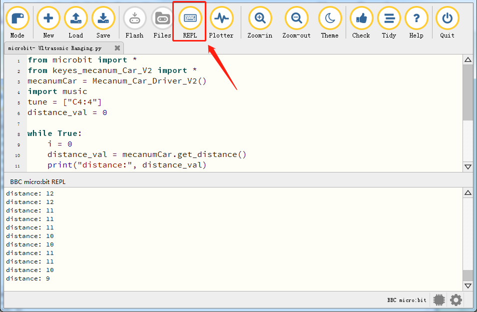
6. Test Result
After downloading the code to the board successfully and don’t plug off the USB cable. Click“REPL”and then press the reset button.
The distance value of obstacle will be displayed, as shown below.
When the distance is less than 10cm, the passive buzzer of smart will emit sound.
7. Code Explanation
Project 18.2:Ultrasonic Avoidance
1. Description
In this project, we will integrate an ultrasonic sensor and a car to make an ultrasonic avoidance car.
Its principle is to detect the distance between the car and obstacle via the ultrasonic sensor to control the motion of smart car.
2. Preparation
Insert micro:bit board into the slot of keyestudio 4WD Mecanum Robot CarV2.0
Place batteries into battery holder
Dial power switch to ON end
Connect micro:bit to the computer via an USB cable
Open the offline version of Mu.
3. Flow Chart
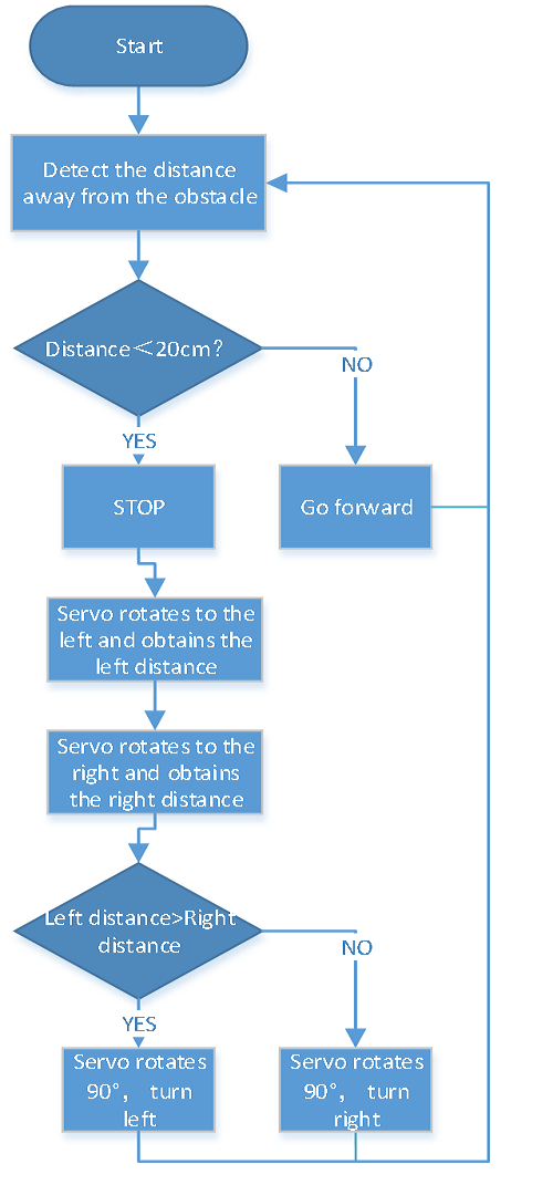
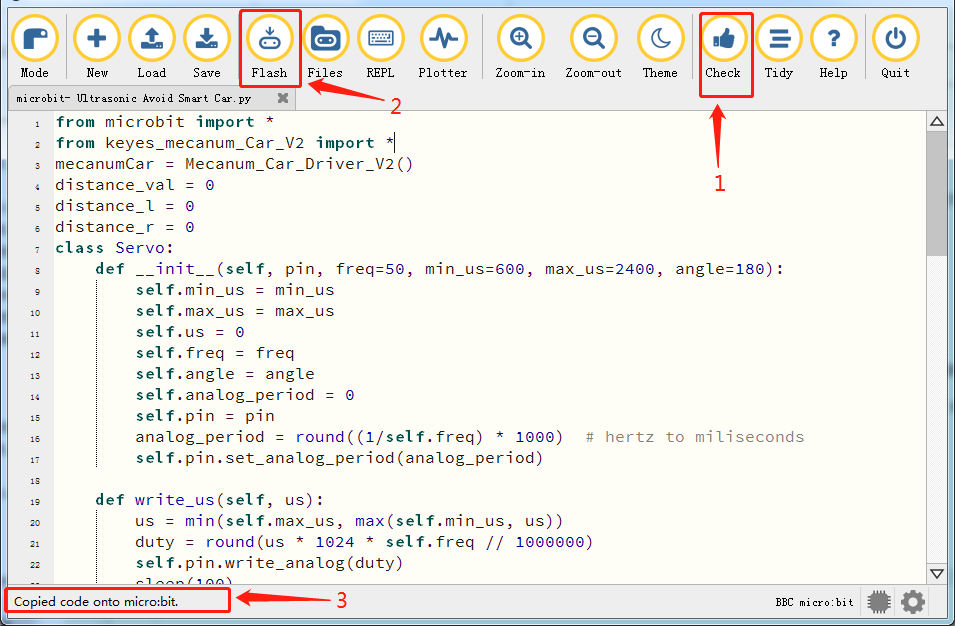
4. Test Code
Enter Mu software and open the file“Ultrasonic Avoid Smart Car.py”to import code. You can also input code in the edit window yourself.
(Note: All English words and symbols must be written in English.)
Click“Files”to import“keyes_mecanum_Car_V2.py“library file to micro:bit .
Click“Check”to examine errors in the code. The program proves wrong if underlines and cursors are shown.
If the code is correct, connect the micro:bit to your computer and click“Flash”to download the code to the micro:bit board.
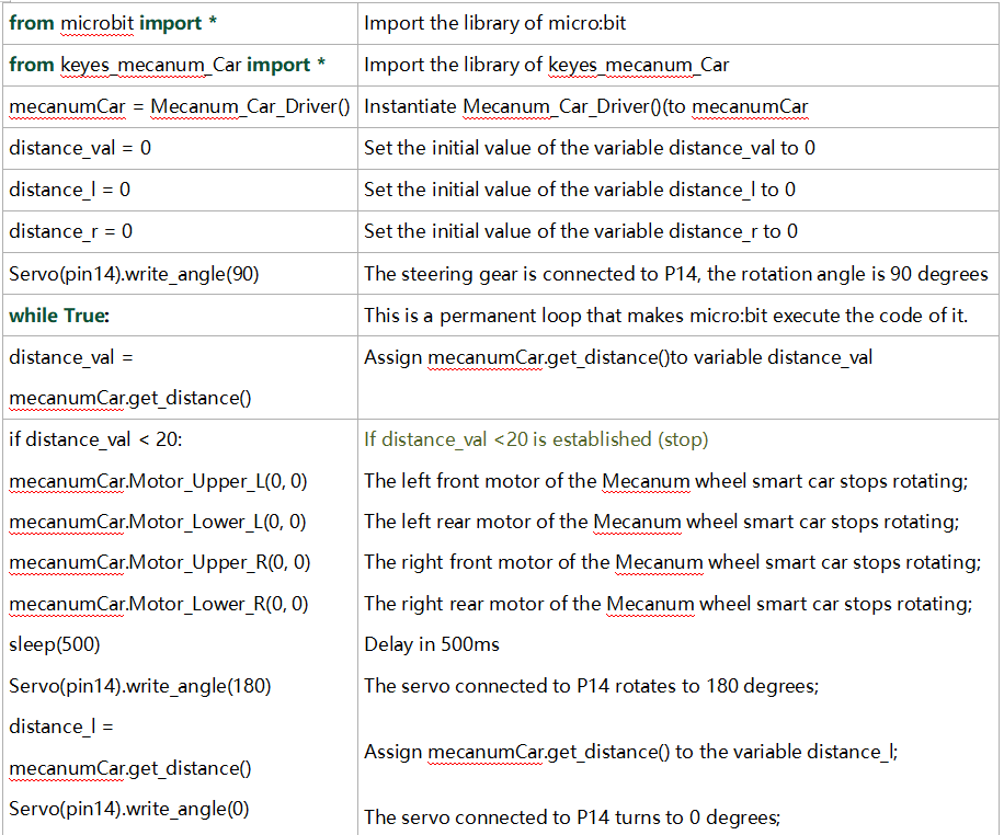
from microbit import *
from keyes_mecanum_Car_V2 import *
mecanumCar = Mecanum_Car_Driver_V2()
distance_val = 0
distance_l = 0
distance_r = 0
class Servo:
def __init__(self, pin, freq=50, min_us=600, max_us=2400, angle=180):
self.min_us = min_us
self.max_us = max_us
self.us = 0
self.freq = freq
self.angle = angle
self.analog_period = 0
self.pin = pin
analog_period = round((1/self.freq) * 1000) # hertz to miliseconds
self.pin.set_analog_period(analog_period)
def write_us(self, us):
us = min(self.max_us, max(self.min_us, us))
duty = round(us * 1024 * self.freq // 1000000)
self.pin.write_analog(duty)
sleep(100)
self.pin.write_analog(0)
def write_angle(self, degrees=None):
if degrees is None:
degrees = math.degrees(radians)
degrees = degrees % 360
total_range = self.max_us - self.min_us
us = self.min_us + total_range * degrees // self.angle
self.write_us(us)
Servo(pin14).write_angle(90)
while True:
distance_val = mecanumCar.get_distance()
if distance_val < 20:
mecanumCar.Motor_Upper_L(0, 0)
mecanumCar.Motor_Lower_L(0, 0)
mecanumCar.Motor_Upper_R(0, 0)
mecanumCar.Motor_Lower_R(0, 0)
sleep(500)
Servo(pin14).write_angle(180)
sleep(500)
distance_l = mecanumCar.get_distance()
sleep(500)
Servo(pin14).write_angle(0)
sleep(500)
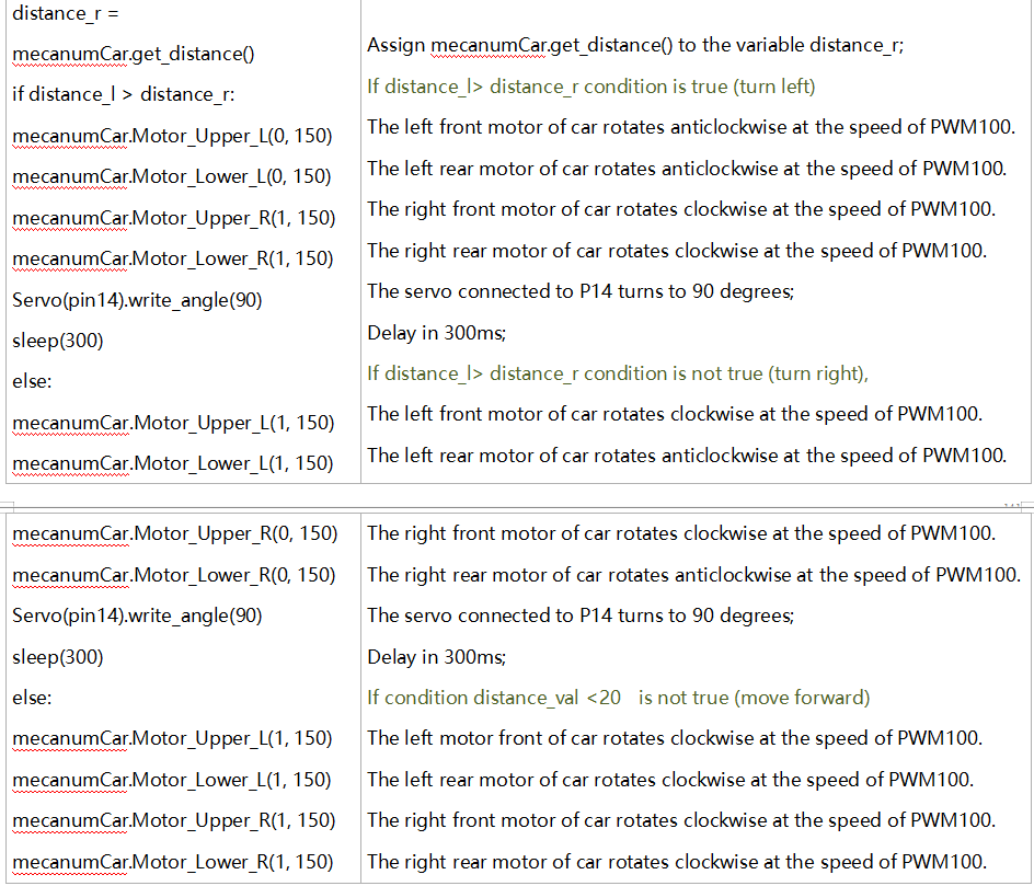
distance_r = mecanumCar.get_distance()
sleep(500)
if distance_l > distance_r:
mecanumCar.Motor_Upper_L(0, 100)
mecanumCar.Motor_Lower_L(0, 100)
mecanumCar.Motor_Upper_R(1, 100)
mecanumCar.Motor_Lower_R(1, 100)
Servo(pin14).write_angle(90)
sleep(300)
else:
mecanumCar.Motor_Upper_L(1, 100)
mecanumCar.Motor_Lower_L(1, 100)
mecanumCar.Motor_Upper_R(0, 100)
mecanumCar.Motor_Lower_R(0, 100)
Servo(pin14).write_angle(90)
sleep(300)
else:
mecanumCar.Motor_Upper_L(1, 100)
mecanumCar.Motor_Lower_L(1, 100)
mecanumCar.Motor_Upper_R(1, 100)
mecanumCar.Motor_Lower_R(1, 100)
5. Test Result
After downloading the code to the board successfully, external power supply(turn the DIP switch to ON),and press the reset button on micro:bit.
When the obstacle distance is greater than 20cm, the car goes forward ; on the contrary, the smart car turns left.
6. Code Explanation
Project 18.3:Ultrasonic Following
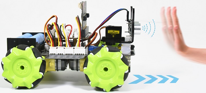
1. Description
In previous lesson, we’ve learned the basic principle of line tracking sensor. Next, we will combine the ultrasonic sensor with the car to make an ultrasonic following car.
The ultrasonic sensor detects the obstacle distance and control the motion status of car.
2. Preparation
Insert micro:bit board into the slot of keyestudio 4WD Mecanum Robot CarV2.0
Place batteries into battery holder
Dial power switch to ON end
Connect micro:bit to the computer via an USB cable
Open the offline version of Mu.
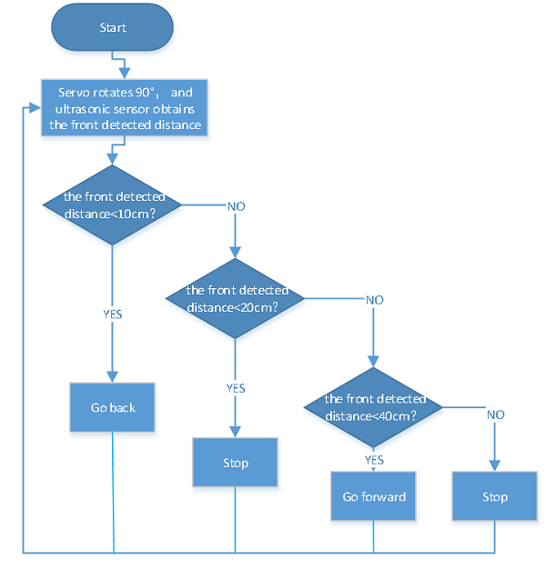
2. Flow Chart
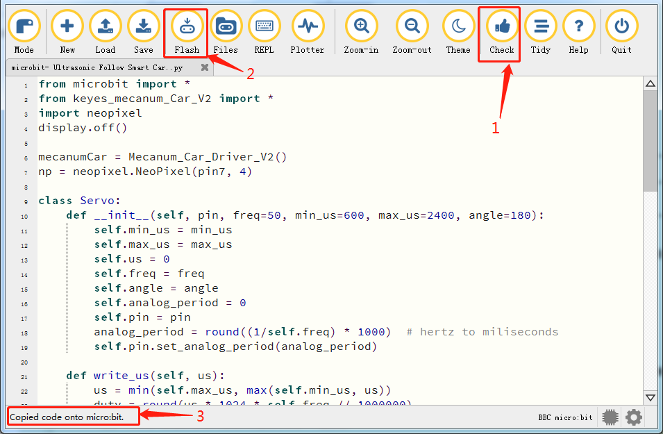
3. Test Code
Enter Mu software and open the file“Ultrasonic Follow Smart Car.py”to import code. You can also input code in the edit window yourself.
(Note: All English words and symbols must be written in English.)
Click“Files”to import“keyes_mecanum_Car_V2.py“library file to micro:bit.
Click“Check”to examine errors in the code. The program proves wrong if underlines and cursors are shown.
If the code is correct, connect the micro:bit to your computer and click“Flash”to download the code to the micro:bit board.
from microbit import *
from keyes_mecanum_Car_V2 import *
import neopixel
display.off()

mecanumCar = Mecanum_Car_Driver_V2()
np = neopixel.NeoPixel(pin7, 4)

class Servo:
    def __init__(self, pin, freq=50, min_us=600, max_us=2400, angle=180):
        self.min_us = min_us
        self.max_us = max_us
        self.us = 0
        self.freq = freq
        self.angle = angle
        self.analog_period = 0
        self.pin = pin
        analog_period = round((1/self.freq) * 1000)  # hertz to miliseconds
        self.pin.set_analog_period(analog_period)

    def write_us(self, us):
        us = min(self.max_us, max(self.min_us, us))
        duty = round(us * 1024 * self.freq // 1000000)
        self.pin.write_analog(duty)
        sleep(100)
        self.pin.write_analog(0)

    def write_angle(self, degrees=None):
        if degrees is None:
            degrees = math.degrees(radians)
        degrees = degrees % 360
        total_range = self.max_us - self.min_us
        us = self.min_us + total_range * degrees // self.angle
        self.write_us(us)

Servo(pin14).write_angle(90)

while True:
    distance_val = 0
    distance_val = mecanumCar.get_distance()
    if distance_val >= 20 and distance_val <= 40:
        mecanumCar.Motor_Upper_L(1, 80)
        mecanumCar.Motor_Lower_L(1, 80)
        mecanumCar.Motor_Upper_R(1, 80)
        mecanumCar.Motor_Lower_R(1, 80)
        for pixel_id1 in range(0, len(np)):
            np[pixel_id1] = (255, 0, 0)
            np.show()
    if distance_val <= 10:
        mecanumCar.Motor_Upper_L(0, 80)
        mecanumCar.Motor_Lower_L(0, 80)
        mecanumCar.Motor_Upper_R(0, 80)
        mecanumCar.Motor_Lower_R(0, 80)
        for pixel_id1 in range(0, len(np)):
            np[pixel_id1] = (255, 255, 0)
            np.show()
    if distance_val > 10 and distance_val < 20 or distance_val > 40:
        mecanumCar.Motor_Upper_L(0, 0)
        mecanumCar.Motor_Lower_L(0, 0)
        mecanumCar.Motor_Upper_R(0, 0)
        mecanumCar.Motor_Lower_R(0, 0)
        for pixel_id1 in range(0, len(np)):
            np[pixel_id1] = (255, 255, 255)
            np.show()
4. Test Result
After downloading the code to the board successfully, external power supply(turn the DIP switch to ON), and press the reset button on micro:bit.
The smart car could follow the obstacle to move and 4 WS2812 RGB lights will display different colors.
Note: the obstacle can only move in front of smart car.
5. Code Explanation
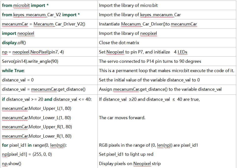
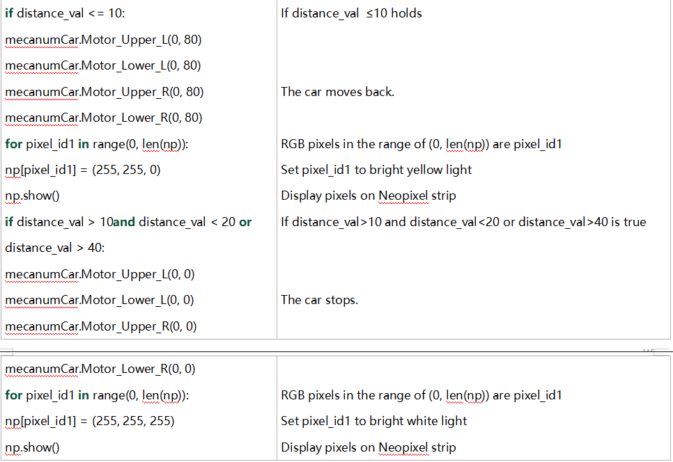
Resources
1. BBC microbit MicroPython:https://microbit-micropython.readthedocs.io/en/latest/tutorials/introduction.html
2. MicroPython:https://docs.openmv.io/reference/index.html
3. math library:https://docs.openmv.io/library/math.html
Common Problem
1. The car has no reaction
Please check whether the batteries are sufficient
Please check whether the wirings are correct
2. Computers can’t recognize the USB ports
Please ensure whether the microbit driver is installed
Please check whether the USB wire is in good condition.
3. Code fails to burn and dot matrix displays expressions
Please check whether the keyes_mecanum_Car_V2.py library file is imported